Safe Operation Practices • Set-Up • Operation • Maintenance • Service • Troubleshooting • Warranty Operator’s Manual Single-Stage Snow Thrower — Squall 2100 WARNING READ AND FOLLOW ALL SAFETY RULES AND INSTRUCTIONS IN THIS MANUAL BEFORE ATTEMPTING TO OPERATE THIS MACHINE. FAILURE TO COMPLY WITH THESE INSTRUCTIONS MAY RESULT IN PERSONAL INJURY. TROY-BILT LLC, P.O. BOX 361131 CLEVELAND, OHIO 44136-0019 Printed In USA Form No.
1 To The Owner Thank You Thank you for purchasing a Snow Thrower manufactured by Troy-Bilt LLC. It was carefully engineered to provide excellent performance when properly operated and maintained. Please read this entire manual prior to operating the equipment. It instructs you how to safely and easily set up, operate and maintain your machine. Please be sure that you, and any other persons who will operate the machine, carefully follow the recommended safety practices at all times.
Important Safe Operation Practices 2 WARNING! This symbol points out important safety instructions which, if not followed, could endanger the personal safety and/or property of yourself and others. Read and follow all instructions in this manual before attempting to operate this machine. Failure to comply with these instructions may result in personal injury. When you see this symbol.
Safe Handling of Gasoline 5. To avoid personal injury or property damage use extreme care in handling gasoline. Gasoline is extremely flammable and the vapors are explosive. Serious personal injury can occur when gasoline is spilled on yourself or your clothes which can ignite. Wash your skin and change clothes immediately. Never run an engine indoors or in a poorly ventilated area. Engine exhaust contains carbon monoxide, an odorless and deadly gas. 6.
Maintenance & Storage Do not modify engine 1. Never tamper with safety devices. Check their proper operation regularly. Refer to the maintenance and adjustment sections of this manual. 2. Before cleaning, repairing, or inspecting machine disengage all control levers and stop the engine. Wait until the auger/impeller come to a complete stop. Disconnect the spark plug wire and ground against the engine to prevent unintended starting. To avoid serious injury or death, do not modify engine in any way.
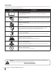
Safety Symbols This page depicts and describes safety symbols that may appear on this product. Read, understand, and follow all instructions on the machine before attempting to assemble and operate. Symbol Description READ THE OPERATOR’S MANUAL(S) Read, understand, and follow all instructions in the manual(s) before attempting to assemble and operate WARNING— ROTATING BLADES Keep hands out of inlet and discharge openings while machine is running.
3 Assembly & Set-Up Contents of Carton • Two Ignition Keys • One 20 oz. Bottle 5W-30 Oil NOTE: All references to the left or right side of the snow thrower are from the operator’s position. Any exceptions will be noted. 2. • One Snow Thrower Operator’s Manual Tighten the wing knobs to secure the handle in place. See Fig. 3-2. Assembly Positioning the Upper Handle 1. Pivot the upper handle into the operating position making sure not to pinch the cable in the process, as illustrated in Fig.
Adding Fuel Adding Oil WARNING! Use extreme care when handling gasoline. Gasoline is extremely flammable and the vapors are explosive. Never fuel the machine indoors or while the engine is hot or running. Extinguish cigarettes, cigars, pipes and other sources of ignition. CAUTION: The engine is shipped without oil in the engine. You must fill the engine with oil before operating. Running the engine with insufficient oil can cause serious engine damage and void the engine warranty. 1.
Adjustments Chute Assembly The pitch of the chute assembly controls the angle at which the snow is thrown. 1. Loosen the wing knob found on the left side of the chute assembly and pivot the upper chute upward or downward to the desired pitch. Retighten the wing knob before operating the snow thrower. 2. Position the chute assembly opening by using the chute handle to throw the snow in the desired direction. See Fig. 3-5.
4 Controls and Features Auger Control Recoil Starter Gasoline Cap Chute Control Handle Chute Assembly Ignition Key Oil Fill Primer Gasoline Cap Oil Fill Throttle Control Choke Control Shave Plate Oil Drain Auger Choke Lever Activating the choke control closes the choke plate on carburetor and aids in starting engine. Primer Pressing primer forces fuel directly into engine’s carburetor to aid in cold-weather starting.
Auger When engaged, the augers rotation draws snow into the auger housing and throws it out the discharge chute. Rubber paddles on the augers also aid in propelling the snow thrower as they come in contact with the pavement. Auger Control Located on the upper handle, the auger control handle is used to engage and disengage drive to the auger. Squeeze the control handle against the upper handle to engage the auger; release it to disengage.
5 Operation Starting the Engine 3. WARNING! Always keep hands and feet clear of moving parts. Do not use a pressurized starting fluid. Vapors are flammable. Plug the extension cord into the electric outlet located on the plastic shroud. Plug the other end of extension cord into a three-prong 120-volt, grounded, AC outlet in a wellventilated area. See Fig. 5-2. NOTE: Allow the engine to warm up for a few minutes after starting.
Recoil Starter Caution: Do not pull the starter handle while the engine running. To Engage Augers 1. To engage the augers and start throwing snow, squeeze the auger control against the handle. Release to stop the augers. Engaging the Drive WARNING! To avoid unsupervised engine operation, never leave the engine unattended while running. Turn the engine off after use and remove ignition key 1. Insert the ignition key fully into the slot, Fig. 5-1. Make sure it snaps into place.
6 Maintenance & Adjustments Adjustments Control Cable WARNING! Before Servicing, repairing or inspecting the snow thrower, disengage the auger control. Stop the engine and remove the key to prevent unintended starting. Shave Plate 1. To check the adjustment of the shave plate, place the machine on a level surface. The wheels, shave plate and augers should all contact the level surface. Note that if the shave plate is adjusted too high, snow may blow under the housing.
7 Engine Maintenance WARNING! To prevent accidental start-up, shut off the engine and remove the ignition key before performing any type of engine maintenance. Periodic inspection and adjustment of the engine is essential if high level performance is to be maintained. Regular maintenance will also ensure a long service life. The required service intervals and the type of maintenance to be performed are described in the table below. Follow the hourly or calendar intervals, whichever occur first.
Changing Engine Oil NOTE: Check the oil level before each use and after every five hours of operation to be sure the correct oil level is maintained. Refer to Checking Oil Level in the Operation Section 1. Drain fuel from the tank by running the engine until the fuel tank is empty. Be sure the fuel fill cap is secure. 2. Place a suitable oil collection container under the oil drain plug. 3. Remove the oil drain plug, Figure 7-3.
5. After the spark plug is seated, tighten with a spark plug wrench to compress the washer. NOTE: When installing a new spark plug, tighten 1⁄2-turn after the spark plug seats to compress the washer. When reinstalling a used spark plug, tighten 1⁄8- to 1⁄4-turn after the spark plug seats to compress the washer. caution: The spark plug must be tightened securely. A loose spark plug can become very hot and can damage the engine.
8 Service Replacing Belt 1. To replace the belt follow these instructions and refer to Fig. 7-2: Remove the belt cover by removing the five hex screws that secure it to the frame. See Fig. 7-1. 1 3 Auger Pulley Idler Pulley Belt Keeper Engine Pulley Hex Screws 2 4 Figure 7-2 2. 1. Push down on the idler pulley. Figure 7-1 2. Remove the belt by grasping it from the bottom of the auger pulley and pulling outward. Position the belt on top of the auger pulley and under the belt keeper. 3.
Replacing Auger Paddles The snow thrower auger’s rubber paddles are subject to wear and should be replaced if any signs of excessive wear are present. CautIon: Do NOT allow the auger’s rubber paddles to wear to the point where portions of the metal auger itself can come in contact with the pavement. Doing so can result in serious damage to your snow thrower. To change the rubber paddles, proceed as follows: 1.
9 Troubleshooting Problem Engine Fails to start Engine runs erratic Cause Remedy 1. Fuel tank empty, or stale fuel. 1. Fill tank with clean fresh gasoline. 2. Blocked fuel line. 2. Clean fuel line. 3. Key not inserted all the way. 3. Insert key all the way. 4. Spark plug wire disconnected. 4. Connect wire to spark plug. 5. Faulty spark plug. 5. Clean spark plug, readjust gap, or replace. 6. Engine not primed. 6. Prime engine five to seven times. 7. Engine flooded from excessive priming. 7.
10 Replacement Parts Component Part Number and Description 731-1033 Shave Plate 754-04204 Belt V-Type 735-04032 735-04033 753-04472 Spiral Crescent Rubber Paddle Replacement Kit (includes 4 crescents, 2 paddles and hardware) 731-05632 Key 746-04237 Clutch Cable 951-10292 Spark Plug Phone (800) 800-7310 to order replacement parts or a complete Parts Manual (have your full model number and serial number ready). Parts Manual downloads are also available free of charge at www.mtdproducts.com.
MTD CONSUMER GROUP (MTD) and the United States Environment Protection Agency (U. S. EPA) Emission Control System Warranty Statement (Owner’s Defect Warranty Rights and Obligations) The U. S. EPA and MTD are pleased to explain the emissions control system warranty on your model year 2005 and later small off-road engine. New small off-road engines must be designed, built and equipped to meet the stringent anti-smog standards.
(7) The engine manufacturer is liable for damages to other engine components proximately caused by a failure under warranty of any warranted part. (8) Throughout the engine’s warranty period defined in Subsection (a)(2), MTD will maintain a supply of warranted parts sufficient to meet the expected demand for such parts. (9) Any replacement part may be used in the performance of any warranty maintenance or repairs and must be provided without charge to the owner.
MANUFACTURER’S LIMITED WARRANTY FOR The limited warranty set forth below is given by Troy-Bilt LLC with respect to new merchandise purchased and used in the United States and/or its territories and possessions, and by MTD Products Limited with respect to new merchandise purchased and used in Canada and/or its territories and possessions (either entity respectively, “Troy-Bilt”). c. Service completed by someone other than an authorized service dealer.
Medidas importantes de seguridad • Configuración • Funcionamiento • Mantenimiento • Servicio • Solución de problemas • Garantía Manual del Operador Máquina quitanieve de etapa única — Squall 2100 ADVERTENCIA LEA Y RESPETE TODAS LAS NORMAS DE SEGURIDAD E INSTRUCCIONES INCLUIDAS EN ESTE MANUAL ANTES DE PONER EN FUNCIONAMIENTO ESTA MÁQUINA. SI NO RESPETA ESTAS INSTRUCCIONES PUEDE PROVOCAR LESIONES PERSONALES. TROY-BILT LLC, P.O.
Al propietario 1 Gracias Gracias por comprar una máquina quitanieve fabricada por Troy-Bilt LLC. La misma ha sido diseñada cuidadosamente para brindar excelente rendimiento si se la opera y mantiene correctamente. Por favor lea todo este manual antes de operar el equipo. Le indica cómo configurar, operar y mantener la máquina con seguridad y fácilmente.
2 Medidas importantes de seguridad ¡ADVERTENCIA! La presencia de este símbolo indica que se trata de instrucciones importantes de seguridad que se deben respetar para evitar poner en peligro su seguridad personal y/o material y la de otras personas. Lea y siga todas las instrucciones de este manual antes de poner en funcionamiento esta máquina. Si no respeta estas instrucciones puede provocar lesiones personales. Cuando vea este símbolo.
Manejo seguro de la gasolina Para evitar lesiones personales o daños materiales tenga mucho cuidado cuando trabaje con gasolina. La gasolina es sumamente inflamable y sus vapores pueden causar explosiones. Si se derrama gasolina encima o sobre la ropa se puede lesionar gravemente ya que se puede incendiar. Lávese la piel y cámbiese de ropa de inmediato. a. b. Utilice sólo los recipientes para gasolina autorizados. Apague todos los cigarrillos, cigarros, pipas y otras fuentes de combustión. c.
Mantenimiento y Almacenamiento No modifique el motor 1. Nunca altere los dispositivos de seguridad. Controle periódicamente que funcionen correctamente. Remítase a las secciones de mantenimiento y ajuste de este manual. 2. Antes de realizar la limpieza, reparar o revisar la máquina, desengrane todas las palancas de control y detenga el motor. Espere a que la barrena / impulsor se detenga por completo.
Símbolos de Seguridad Esta página describe los símbolos y figuras de seguridad internacionales que pueden aparecer en este producto. Lea el manual del operador para obtener la información terminada sobre seguridad, reunirse, operación y mantenimiento y reparación. Símbolo Descripción LEA EL MANUAL DEL OPERADOR (S) Lea, entienda, y siga todas las instrucciones en el manual (es) antes de intentar reunirse y funcionar.
Montaje y Configuración 3 Contenido de la caja • Dos llaves de encendido • Una botella de 20 oz. de aceite 5W-30 NOTA: Todas las referencias a los lados derecho o izquierdo de la máquina quitanieve se hacen observando la misma desde la posición del operador. En caso de que hubiese una excepción, se especificará claramente. 2. • Un Manual del Operador de la Máquina Quitanieve Ajuste las perillas de aletas para sujetar la barra en su lugar. Vea la Fig. 3-2.
Carga de combustible Procedimiento para agregar aceite ¡ADVERTENCIA! Tenga mucho cuidado al trabajar con gasolina. La gasolina es sumamente inflamable y sus vapores pueden causar explosiones. Nunca agregue combustible a la máquina en interiores ni mientras el motor está caliente o en funcionamiento. Apague cigarrillos, cigarros, pipas y otras fuentes de combustión. PRECAUCIÓN: El motor se envía sin aceite en el motor. Antes de poner la máquina en marcha debe cargar aceite en el motor.
Ajustes Montaje del canal La inclinación del montaje del canal controla el ángulo con el que se arroja la nieve. 1. Afloje la perilla de paletas que se encuentra del lado izquierdo del montaje del canal y gire el canal superior hacia arriba o hacia abajo hasta alcanzar la inclinación deseada. Vuelva a ajustar la perilla de paletas antes de poner la máquina quitanieve en funcionamiento. 2. Posicione la abertura del montaje del canal con la manija del canal para arrojar la nieve en la dirección deseada.
Controles y Características 4 Manija del arrancador de retroceso Llave de encendido Control de la barrena Cebador Tapa de combustible Manija de control Montaje del canal Escape Placa de raspado Palanca del cebador Tapón de llenado de aceite c/ varilla de medición del nivel de aceite Tubo de drenaje del aceite Barrena Palanca del cebador Bujía / Funda de la bujía Manija del arrancador de retroceso Figura 4-1 Arrancador de retroceso La manija del arrancador se utiliza para arrancar el motor manu
Montaje del canal Haga rotar el canal de descarga hacia la izquierda o derecha usando la manija del canal. La inclinación del canal de descarga controla el ángulo con el que se arroja la nieve. Afloje la perilla de aletas del costado del canal de descarga antes de girar el canal de descarga hacia arriba o hacia abajo. Vuelva a ajustar la perilla después de alcanzar la posición deseada.
Funcionamiento Encendido del motor 5 3. ¡ADVERTENCIA! Siempre mantenga las manos y los pies alejados de las partes móviles. No utilice fluidos comprimidos para arrancar. Los vapores son inflamables. Conecte el prolongador al tomacorriente situado en el motor. Conecte el otro extremo del prolongador a un tomacorriente de CA, 120 voltios con conexión a tierra, para tres patas, en un área bien ventilada. Vea la Fig. 5-2. NOTA: Deje que el motor se caliente durante unos minutos tras el arranque.
Arrancador de retroceso 1. ¡ADVERTENCIA! Para evitar que el motor funcione Enganche de la transmisión mientras el motor está en marcha. sin control, nunca lo deje sin vigilancia mientras está en marcha. Apague el motor luego de usarlo y saque la llave de encendido 1. Procedimiento para engranar las barrenas Precaución: No tire de la manija del arrancador Inserte la llave de encendido completamente dentro de la ranura, Figura 5-1. Cerciórese de que calce bien en su lugar.
Mantenimiento y Ajustes Ajustes Cable de control ¡ADVERTENCIA! Antes de realizar tareas de mantenimiento, reparación o inspección en la máquina quitanieve, desengrane el control de la barrena. Apague el motor y retire la llave para evitar el encendido accidental del motor. Placa de raspado 1. 6 Para verificar el ajuste de la placa de raspado, ubique la unidad sobre una superficie nivelada. Las ruedas, la placa de raspado y las barrenas deben tocar la superficie nivelada.
Mantenimiento del motor 7 ¡ADVERTENCIA! Para evitar el arranque La inspección y los ajustes periódicos del motor son esenciales si se desea mantener un alto nivel de desempeño. El mantenimiento regular también garantizará una prolongada vida útil del motor. Los intervalos de mantenimiento requeridos y el tipo de mantenimiento a realizar se describen en la tabla siguiente. Siga los intervalos por hora o calendarios, lo que ocurra primero.
Cambio del aceite del motor NOTA: Verifique el nivel de aceite antes de cada uso y después de cada cinco horas de funcionamiento para cerciorarse que se mantiene el nivel de aceite indicado. Consulte la Verificación del nivel de aceite en la sección Funcionamiento 1. Vacíe el combustible del depósito haciendo funcionar el motor hasta que el depósito de combustible esté vacío. Cerciórese de que el tapón de llenado del combustible está bien ajustado. 2.
5. Una vez que la bujía está colocada en su lugar, apriete con una llave para bujía para comprimir la arandela. NOTA: Cuando instale una bujía nueva, apriete 1⁄2vuelta, después que la bujía se encuentra colocada en su lugar, para comprimir la arandela. Cuando reinstale una bujía usada, ajuste 1⁄8- a 1⁄4de giro, después que la bujía se encuentra colocada en su lugar, a fin de comprimir la arandela. precaución: La bujía debe estar bien ajustada. Si la bujía está floja puede recalentarse y dañar el motor.
Servicio 8 Reemplazo de las correas 1. Para sacar la cubierta de la correa saque los cinco tornillos hexagonales que la sujetan al bastidor. Vea la Fig. 7-1. Para volver a colocar la correa siga estas instrucciones y consulte la Fig. 7-2: 1 3 Polea de la barrena Polea loca Polea del motor Tornillos de cabeza hexagonal Guardacorrea 2 4 Figura 7-2 1. Tire hacia abajo la polea loca. Retire la correa sujetándola por la base de la polea de la barrena y tire hacia afuera. 2.
Reemplazo de las paletas de la barrena Las paletas de caucho de la barrena de la máquina quitanieve se desgastan y se las debe cambiar si se presentan signos de desgaste excesivo. Precaución: NO permita que las paletas de caucho de la barrena se desgasten hasta el punto en que partes de la barrena metálica misma toquen el pavimento. Si esto sucede la máquina quitanieve puede dañarse seriamente. Para cambiar las paletas de caucho proceda de la siguiente manera: 1.
Solución de Problemas Problema El motor no arranca 9 Causa 1. El depósito de combustible está vacío o el combustible se ha echado a perder. 2. La línea del combustible está bloqueada. 3. No se introdujo completamente la llave. 4. Se ha desconectado el cable de la bujía. 5. La bujía no funciona correctamente. 6. El motor no está cebado. 7. El motor está ahogado ya que ha sido cebado demasiado. Solución 1. Llene el depósito con gasolina limpia y nueva. 2. Limpie la línea del combustible. 3.
Notes 10 21
Troy-Bilt LLC (Troy-Bilt) y la Agencia de Protección Medioambiental de Estados Unidos (U. S. EPA) Declaración de Garantía del Sistema de Control de Emisiones (Derechos y obligaciones del propietario según la garantía contra defectos) La U. S. EPA y Troy-Bilt se complacen en explicar la garantía del sistema de control de emisiones de su motor para equipo todo terreno, modelo, año 2005 y versiones posteriores.
(4) La reparación o el reemplazo de cualquier pieza garantizada de conformidad con las disposiciones de la garantía que aquí se estipula se debe realizar en un centro de garantía sin costo alguno para el propietario. (5) Sin perjuicio de las disposiciones de la Subsección (4) anterior, los servicios o reparaciones cubiertos por la garantía deben ser suministrados por todos los centros de distribución de Troy-Bilt que tengan la franquicia para realizar reparaciones y mantenimiento a los motores en cuestión.
GARANTÍA LIMITADA DEL FABRICANTE PARA La siguiente garantía limitada es otorgada por Troy-Bilt LLC con respecto a nuevos productos adquiridos y utilizados en Estados Unidos y/o sus territorios y posesiones, y por MTD Products Limited con respecto a nuevos productos adquiridos y utilizados en Canadá y/o sus territorios y posesiones (cualquiera de las dos entidades, respectivamente, “Troy-Bilt”).