Safe Operation Practices • Set-Up • Operation • Maintenance • Service • Troubleshooting • Warranty Operator’s Manual FLEX™ Mower Deck Attachment — 23AAAA8X711 WARNING READ AND FOLLOW ALL SAFETY RULES AND INSTRUCTIONS IN THIS MANUAL BEFORE ATTEMPTING TO OPERATE THIS MACHINE. FAILURE TO COMPLY WITH THESE INSTRUCTIONS MAY RESULT IN PERSONAL INJURY. TROY-BILT LLC, P.O. BOX 361131 CLEVELAND, OHIO 44136-0019 Printed In USA Form No.
1 To The Owner Thank You Thank you for purchasing the Troy-Bilt FLEX™ Mower Deck Attachment. It was carefully engineered to provide excellent performance when properly operated and maintained. Please read this entire manual prior to operating the equipment. It instructs you how to safely and easily set up, operate and maintain your machine. Please be sure that you, and any other persons who will operate the machine, carefully follow the recommended safety practices at all times.
Important Safe Operation Practices 2 WARNING: This symbol points out important safety instructions which, if not followed, could endanger the personal safety and/or property of yourself and others. Read and follow all instructions in this manual before attempting to operate this machine. Failure to comply with these instructions may result in personal injury. When you see this symbol.
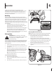
Do not hold on to the mower if you are falling; release the Drive and Attachment Control Levers immediately. 14. a. Step back from mower to fully extend your arms. b. Be sure you are well balanced with sure footing. c. Pull the mower back slowly, no more than half way toward you. d. Repeat these steps as needed. 15. Do not operate the mower while under the influence of alcohol or drugs. 16. Do not engage the self-propelled mechanism while starting the engine. 17.
Service 3. Check the blade and engine mounting bolts at frequent intervals for proper tightness. Also, visually inspect blade for damage (e.g., bent, cracked, worn) Replace blade with the original equipment manufacture’s (O.E.M.) blade only, listed in this manual. “Use of parts which do not meet the original equipment specifications may lead to improper performance and compromise safety!” 4. Mower blades are sharp and can cut. Wrap the blade or wear gloves, and use extra caution when servicing them.
Notice Regarding Emissions Engines which are certified to comply with California and federal EPA emission regulations for SORE (Small Off Road Equipment) are certified to operate on regular unleaded gasoline, and may include the following emission control systems: Engine Modification (EM), Oxidizing Catalyst (OC), Secondary Air Injection (SAI) and Three Way Catalyst (TWC) if so equipped. If a spark arrestor is used, it should be maintained in effective working order by the operator.
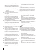
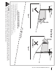
(OK) Figure 1 line Slope Gauge 10° Slope 1 0 ° d a s hed USE THIS SLOPE GAUGE TO DETERMINE IF A SLOPE IS TOO STEEP FOR SAFE OPERATION! To check the slope, proceed as follows: 1. Remove this page and fold along the dashed line. 2. Locate a vertical object on or behind the slope (e.g. a pole, building, fence, tree, etc.) 3. Align either side of the slope gauge with the object (See Figure 1 and Figure 2 ). 4. Adjust gauge up or down until the left corner touches the slope (See Figure 1 and Figure 2). 5.
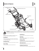
3 Controls & Features Attachment Control Lever Attachment Control Lever Lock Drive Control Lever Deck Lift Lever Caster Wheel Lock Mulch Plug Discharge Chute Grease Fitting Figure 3-1 WARNING! Read and follow all safety rules and instructions in this manual, including the entire Operation section, before attempting to operate this machine. Failure to comply with all safety rules and instructions may result in personal injury.
4 Operation Thank you for purchasing the Troy-bilt FLEX™ mower attachment. This unit is fully assembled and requires no setup. The following instructions will guide you through use and operation of your new attachment, along with maintenance instructions and procedures. Mulch Plug The Troy-bilt FLEX™ mowing attachment is equipped with a mulch plug and special blades already installed on your mowing attachment as standard equipment, which recirculate the grass clippings repeatedly beneath the cutting deck.
Starting And Stopping The Engine • Always be sure of your footing. A slip and fall can cause serious personal injury. Be sure you can control the machine. If you feel you are losing your balance, release the Attachment Control Lever immediately and the blades will stop rotating within three (3) seconds: • Do not mow near drop-offs, ditches or embankments, you could lose your footing or balance. • Do not mow slopes greater than 10 degrees as shown on the slope gauge. • Do not mow on wet grass.
Note: When moving the deck lift lever up and down, the front caster wheels must also be adjusted to coordinate with the deck lift lever. If the deck lift lever is moved into the lowest cutting position, then the front caster wheels must be moved into the highest hole adjustment. Follow this guideline when adjusting the deck height. See Figure 4-4 for reference.
5 Maintenance & Adjustments Maintenance WARNING! Before performing any maintenance or repairs, disengage blades, stop engine and remove key to prevent unintended starting. Engine Refer to the FLEX™ Base Unit Owner’s Manual for all engine maintenance procedures and specific instructions pertaining to your engine. Cleaning the Mower Any fuel or oil spilled on the machine should be wiped off promptly. Do NOT allow debris to accumulate around any part of the machine, especially the belts and pulleys.
Lubrication Engagement Pivot Bracket WARNING! Before lubricating, repairing, or inspecting, always stop the engine and remove the key to prevent unintended starting. Lubricate the engagement pivot bracket once a season with a spray lubricant. See Figure 5-3. In order to access this pivot point, refer to Belt Care in the Service section for the steps for removing the belt covers.
6 Service Cutting Blades WARNING! Shut the engine off and remove ignition key before removing the cutting blades for sharpening or replacement. Protect your hands by using heavy gloves when grasping the blades. WARNING! Periodically inspect the blade and/or spindle for cracks or damage, especially after you’ve struck a foreign object. Do not operate the machine until damaged components are replaced. The cutting blades can be sharpened or replaced. To do so, they must be removed first.
WARNING: An unbalanced blade will cause excessive vibration when rotating at high speeds. It may cause damage to mower and could break causing personal injury. 8. Slide the blade onto the spindle shaft with the side marked “Bottom” (or with part number) facing the ground when the mower is in the operating position. 9. Replace the hex bolt and tighten to torque: 450 in. lbs. min., 600 in. lbs. max. 3. Remove the lower belt cover by removing the four screws that secure it as shown in Figure 6-5.
To replace the upper and lower deck belts: 4. Remove the left belt keeper shown in Figure 6-8 by removing the two hex screws that secure it. 5. Loosen, but do not remove, the idler pulley used on the top deck belt. 6. Remove the cotter pin from the height adjustment link, and slide the link off of the height adjustment pivot assembly. See Figure 6-9. Three belt keepers must first be removed, followed by removal of the upper, then lower belts.
7. Remove the top belt from the drive spindle by working the belt around the spindle pulley as shown in Figure 6-10. 9. Relieve tension on the lower belt by moving the idler arm and tension pulley inward as shown in Figure 6-12. 10. Remove the lower belt by working it off of the image left pulley above first, then the other pulley and off of the machine. 11. Replace the lower belt, then the upper belt. 12. Repeat Steps 1 through 9 in the reverse order to complete the belt replacement process.
7 Troubleshooting Problem Excessive vibration Mower will not mulch grass Uneven cut 18 Cause Remedy 1. Cutting blade loose or unbalanced. 1. Tighten blade and spindle. 2. Damaged or bent cutting blade. 2. Replace blade. 1. Wet grass. 1. Do not mulch when grass is wet. 2. Excessively high grass. 2. Mow once at a high cutting height, then mow again at desired height or make a narrower cutting swath. 3. Dull blade. 3. Sharpen or replace blade. 1. Dull blade. 1. Sharpen or replace blade. 2.
8 Replacement Parts Component Part Number and Description 954-05103 Belt 942-05130 Deck Blade 634-04606 Wheel 731-10510 Discharge Chute 687-05133 Mulch Plug 731-10534A Trail Shield Phone (800) 828-5500 or (330) 558-7220 to order replacement parts or a complete Parts Manual (have your full model number and serial number ready). Parts Manual downloads are also available free of charge at www.troybilt.com.
LIMITED WARRANTY FOR FLEX ATTACHMENT PRODUCT The limited warranty set forth herein is given by Troy-Bilt LLC to the Initial Purchaser (as defined herein) with respect to a new Troy-Bilt-branded FLEX attachment product consisting of one of the following four (4) attachments to the FLEX Power Base (referred to hereafter as the “Attachment”): (i) wide area mower, (ii) snow-thrower, (iii) pressure washer or (iv) leaf blower.
Medidas de seguridad • Configuración • Funcionamiento • Mantenimiento • Servicio • Solución de problemas • Garantía Manual del Operador Accesorio de plataforma de corte FLEX™ — 23AAAA8X711 ADVERTENCIA LEA Y OBSERVE TODAS LAS NORMAS E INSTRUCCIONES DE SEGURIDAD INCLUIDAS EN ESTE MANUAL ANTES DE PONER EN FUNCIONAMIENTO LA MÁQUINA. SI NO SIGUE ESTAS INSTRUCCIONES PUEDE PROVOCAR LESIONES PERSONALES. TROY-BILT LLC, P.O. BOX 361131 CLEVELAND, OHIO 44136-0019 Impreso en EE.UU. Formulario N.
1 Al propietario Gracias Gracias por comprar el Accesorio de plataforma de corte FLEX™ Troy-Bilt. Se ha diseñado cuidadosamente para brindar excelente rendimiento si se opera y mantiene correctamente. Por favor lea todo este manual antes de hacer funcionar el equipo. El manual le indica cómo configurar, operar y mantener la máquina de manera fácil y segura.
2 Importantes medidas de seguridad ADVERTENCIA: La presencia de este símbolo indica que se trata de instrucciones de seguridad importantes que se deben respetar para evitar poner en peligro su seguridad personal y/o material y la de otras personas. Lea y cumpla todas las instrucciones de este manual antes de intentar operar esta máquina. Si no respeta estas instrucciones puede provocar lesiones personales. Cuando vea este símbolo.
No se sostenga de la cortadora si se está cayendo, suelte inmediatamente las palancas de control de la transmisión y el accesorio. 14. a. Retroceda de la cortadora hasta estirar completamente los brazos. b. Asegúrese que tiene buen equilibrio y está bien parado. c. Jale la cortadora lentamente hacia usted, no más de la mitad de la distancia entre usted y la cortadora. d. Repita estos pasos tantas veces como sea necesario.
Servicio 3. Revise los pernos de montaje de la cuchilla y del motor a intervalos frecuentes para verificar que estén bien apretados. Además, debe inspeccionar visualmente la cuchilla en busca de daños (por ejemplo, abolladuras, desgaste, roturas). Reemplace la cuchilla únicamente con equipo original del fabricante (OEM) listado en este manual. “El uso de repuestos que no cumplen con las especificaciones del equipo original puede resultar en rendimiento inadecuado y puede comprometer la seguridad.” 4.
Aviso referido a emisiones Los motores que están certificados y cumplen con las normas sobre emisiones federales EPA y de California para SORE (Equipos pequeños todo terreno) están certificados para funcionar con gasolina sin plomo común y pueden incluir los siguientes sistemas de control de emisiones: Modificación de motor (EM), catalizador oxidante (OC), inyección de aire secundaria (SAI) y catalizador de tres vías (TWC) si están instalados.
(OK) (OK) Figura Figure 1 Indicador Slope de pendiente Gauge Pendiente 10° Slope de 10° Figura Figure 22 (DEMASIADO EMPINADA) (TOO STEEP) L1ín0e°a d dae gu s i o h n e e d s l i nae 10° ¡USE ESTE INDICADOR DE PENDIENTE PARA DETERMINAR SI UNA PENDIENTE ES DEMASIADO EMPINADA PARA OPERAR CON SEGURIDAD USE THIS SLOPE GAUGE TO DETERMINE Para comprobar la pendiente, proceda de la siguiente manera: IF A SLOPE IS TOO STEEP FOR SAFE OPERATION! 1. Retire esta página y pliéguela por la línea de guiones.
3 Controles y Características Palanca de control del accesorio Bloqueo de la palanca de control del accesorio Palanca de control de la transmisión Palanca de elevación de la plataforma Traba de la ruedita Clavija para abono Canal de descarga Engrasador Figura 3-1 ¡ADVERTENCIA! Lea y observe todas las normas e instrucciones de seguridad de este manual, incluida toda la sección de funcionamiento, antes de poner esta máquina en funcionamiento.
4 Funcionamiento Gracias por comprar el accesorio cortador de césped FLEX™ Troy-Bilt. Esta unidad está completamente ensamblada y no requiere ajustes. Las siguientes instrucciones le guiarán en el uso y la operación de su nuevo accesorio, junto con las instrucciones y los procedimientos de mantenimiento.
Arranque y detención del motor • Asegúrese siempre de estar bien parado. Si resbala y cae puede lesionarse gravemente. Asegúrese de poder controlar la máquina. Si siente que pierde el equilibrio, suelte inmediatamente la palanca de control del accesorio y las cuchillas dejarán de girar en tres (3) segundos: • No corte el césped cerca de caídas, zanjas o terraplenes, puede perder el equilibrio. • No corte en pendientes mayores de 10° como ilustra el indicador de pendientes.
Bloqueo de giro de las ruedas delanteras Las dos ruedas delanteras del accesorio cortador de césped incluyen una función de giro libre que se usa para dirigir la unidad a fin de rodear objetos y una función de bloqueo para cortar césped en línea recta o atravesando pendientes (nunca subiendo o bajando pendientes). Para trabar y destrabar las ruedas delanteras: 1. Tire de la varilla de seguridad hacia arriba, como se indica en la Figura 4-5. 2.
5 Mantenimiento y Ajustes Mantenimiento ¡ADVERTENCIA! Antes de realizar cualquier mantenimiento o reparación, desconecte las cuchillas, apague el motor y retire la llave para evitar el encendido accidental del motor. Motor Consulte el manual del operador de la unidad base FLEX™ para obtener todos los procedimientos de mantenimiento del motor y las instrucciones específicas relativas a su motor. Limpieza de la cortadora Si se derrama combustible o aceite sobre la máquina, debe limpiarse de inmediato.
Lubricación Pivot Compromiso Soporte ¡ADVERTENCIA! Antes de realizar tareas de lubricación, reparación o inspección, siempre debe parar el motor y retirar la llave para evitar el encendido accidental del motor. Lubrique la temporada oz compromiso soporte de pivote con un lubricante en aerosol. Vea la Figura 5-3. Para acceder a este punto de giro, Consulte Cuidado de la correa en la sección Servicio para los pasos del apartado Extracción de las cubiertas de la correa.
6 Servicio Cuchillas de corte ¡ADVERTENCIA! Apague el motor y extraiga la llave de encendido antes de retirar las cuchillas de corte para afilarlas o reemplazarlas. Proteja sus manos utilizando guantes reforzados cuando sujete las cuchillas. ¡ADVERTENCIA! Inspeccione periódicamente la cuchilla y/o el husillo en busca de rajaduras o daños, especialmente después de golpear un objeto extraño. No opere la máquina hasta después de haber reemplazado los componentes dañados.
ADVERTENCIA: Si la cuchilla está desequilibrada causará demasiada vibración al rotar a altas velocidades. Puede dañar la cortadora de césped y se puede romper, causando lesiones personales. 8. Deslice la cuchilla con el lado marcado “Bottom” (inferior) (o con un número de pieza) del eje de husillo orientado hacia el piso cuando la podadora está en posición de funcionamiento. 9. Reemplace el perno hexagonal y ajuste hasta el par: 450 lbpulg como mínimo, 600 lb-pulg como máximo. 3.
A fin de reemplazar las correas de plataforma superior e inferior: 4. Extraiga el guardacorreas izquierdo, que se muestra en la Figura 6-8, para lo que debe extraer los dos tornillos hexagonales que lo sujetan. 5. Afloje, pero no saque, la correa loca que se utiliza en la correa superior de la plataforma. 6. Retire el pasador desde el enlace de ajuste de altura, y el tobogán de enlace fuera del pivote conjunto de ajuste de altura. Vea la Figura 6-9.
7. Extraiga la correa superior del husillo de transmisión, para lo que debe pasarla alrededor de la polea del husillo como se indica en la Figura 6-10. 9. Afloje la tensión de la correa inferior para lo que debe mover el brazo de polea loca y la polea tensora hacia adentro como se indica en la Figura 6-12. 10. Extraiga la correa inferior. Para hacerlo, pásela hacia afuera primero de la polea izquierda precedente, luego de la otra polea y sáquela de la máquina. 11.
7 Solución de Problemas Problema Solución Demasiada vibración 1. Cuchilla de corte floja o descentrada. 1. Apriete la cuchilla y el husillo. 2. Cuchilla dañada o doblada. 2. Reemplace la cuchilla. La cortadora de césped no procesa los recortes como abono 1. Pasto mojado. 1. No procese abono cuando el pasto está mojado. 2. Césped demasiado alto. 2. Corte una vez con altura de corte elevada y luego vuelva a cortar el césped a la altura deseada, o haga una pasada de corte más angosta. 3.
8 Piezas de reemplazo Componente Número de pieza y Descripción 954-05103 Correa 942-05130 Cuchilla de plataforma 634-04606 Rueda 731-10510 Conjunto de canal de descarga 687-05133 Tolva de abono 731-10534A Escudo posterior Llame por teléfono al (800) 828-5500 o (330) 558-7220 para solicitar piezas de reemplazo o un Manual de Repuestos completo (tenga el número de modelo y número de serie de su máquina a mano). En www.troybilt.com también podrá descargar el Manual de Repuestos sin cargo alguno.
GARANTÍA LIMITADA PARA EL ACCESORIO FLEX La garantía limitada que se estable en el presente documento es otorgada por Troy-Bilt LLC al comprador inicial (como se define en este documento) en relación con el nuevo accesorio FLEX Troy-Bilt que está integrado por uno de los siguientes cuatro (4) accesorios de la base de potencia FLEX (identificado en adelante como el "Accesorio"): (i) cortadora de césped con capacidad para superficies amplias, (ii) máquina quitanieve, (iii) lavadora a presión o (iv) soplador d