Safe Operation Practices • Set-Up • Operation • Service • Troubleshooting • Warranty Operator’s Manual FLEX™ Snow Thrower Attachment WARNING READ AND FOLLOW ALL SAFETY RULES AND INSTRUCTIONS IN THIS MANUAL BEFORE ATTEMPTING TO OPERATE THIS MACHINE. FAILURE TO COMPLY WITH THESE INSTRUCTIONS MAY RESULT IN PERSONAL INJURY. NOTE: This Operator’s Manual covers several models. Features may vary by model. Not all features in this manual are applicable to all models and the model depicted may differ from yours.
1 To The Owner Thank You Thank you for purchasing the Troy-Bilt FLEX™ Snow Thrower Attachment. It was carefully engineered to provide excellent performance when properly operated and maintained. Please read this entire manual prior to operating the equipment. It instructs you how to safely and easily set up, operate and maintain your machine. Please be sure that you, and any other persons who will operate the machine, carefully follow the recommended safety practices at all times.
2 Important Safe Operation Practices WARNING! This symbol points out important safety instructions which, if not followed, could endanger the personal safety and/or property of yourself and others. Read and follow all instructions in this manual before attempting to operate this machine. Failure to comply with these instructions may result in personal injury. When you see this symbol.
7. Muffler and engine become hot and can cause a burn. Do not touch. Keep children away. 8. Exercise extreme caution when operating on or crossing gravel surfaces. Stay alert for hidden hazards or traffic. 9. Exercise caution when changing direction and while operating on slopes. Do not operate on steep slopes. 10. Plan your snow-throwing pattern to avoid discharge towards windows, walls, cars etc. Thus, avoiding possible property damage or personal injury caused by a ricochet. 11.
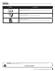
Safety Symbols This page depicts and describes safety symbols that may appear on this product. Read, understand, and follow all instructions on the machine before attempting to assemble and operate. Symbol Description READ THE OPERATOR’S MANUAL(S) Read, understand, and follow all instructions in the manual(s) before attempting to assemble and operate. WARNING— ROTATING AUGER Avoid injury from rotating auger. Keep hands, feet, and clothing away.
3 Assembly & Set-Up Assembly 3. Clip the discharge chute handle onto the discharge chute, as shown in Figure 3-3. 4. Place some of the white lithium grease provided on the chute band as shown in Figure 3-4. Installing the Discharge Chute 6. With the discharge chute positioned to the right as shown, install the chute band by lining up the notches in the front with the band, and making certain to fit the discharge chute inside the channel of the chute band, as detailed in the inset of Figure 3-6. 7.
NOTE: If the installation has been completed properly, a click! click! click! sound will be heard when rotating the chute to the left and right. See Figure 3-8. To adjust the skid shoes: Shear Pins 1. Loosen the four hex nuts (two on each side) and carriage bolts. Move skid shoes to desired position. See Figure 3-9. 2. Make certain the entire bottom surface of skid shoe is against the ground to avoid uneven wear on the skid shoes.
4 Controls & Operation Couple Snow Thrower Attachment with Power Base Attachment Control Lever 1. With the kickstand UP on the FLEX™ Power Base, as shown in Figure 4-2, roll it over to the snow thrower attachment. 2. Tip the FLEX™ Power Base forward, engaging the top mounting tab with the mounting handle on the snow thrower attachment. See Figure 4-3. 3.
Uncouple Snow Thrower Attachment from Power Base Fully stop the power unit engine before attempting to perform any maintenance steps or uncoupling of the attachment. Never attempt to uncouple the power base from the snow thrower attachment WITH the engine running. WARNING! Always turn off the FLEX™ Power Base engine and remove the key prior to attempting to replace the shear pins or uncoupling of the power base from the attachment. 1. Put the kickstand down. 2.
5 Service Maintenance 2. Remove the plastic belt cover on the snow thrower attachment by removing the two selftapping screws that secure it. See Figure 5-1. 3. Looking at the rear mounting plate of the snow thrower attachment, loosen (but do not remove) the left side hex screw shown in Figure 5-2. General Recommendations • Always observe safety rules when performing any type of maintenance.
Augers 3. Rotate the discharge chute to the right as shown in Figure 5-6. 4. Remove the two self-tapping screws securing the belt cover to the auger housing and lift the belt cover up and away from the housing. Set belt cover and screws aside and save. See Figure 5-7. The augers are secured to the spiral shaft with four shear pins and cotter pins. If you hit a foreign object or ice jam, the snow thrower is designed so that the pins may shear. 6.
6 Troubleshooting Problem 12 Cause Remedy Excessive vibration or noise when the Attachment Control Lever is applied. 1. One or more of the clutch bumpers is missing or worn. 1. Replace the three clutch bumpers with replacement kit part no. 753-08457. Augers continue to rotate 1. Cable out of adjustment. 1. Adjust the auger control cable as shown in the Maintenance Section under “Adjusting the Auger Drive Cable”. Unit fails to discharge snow 1. Chute assembly clogged. 1.
7 Replacement Parts Part Number and Description Component 954-05071 Auger Drive Belt 738-04124A 714-04040 Shear Pin, 1.50 Bow-tie Cotter Pin 784-5580 Skid Shoe, Standard (steel) 931-2643 Chute Clean-out Tool 790-00121 Shave Plate 753-08457 Clutch Bumper Kit (6) Phone (800) 828-5500 to order replacement parts or a complete Parts Manual (have your full model number and serial number ready). Parts Manual downloads are also available free of charge at www.troybilt.com.
LIMITED WARRANTY FOR FLEX ATTACHMENT PRODUCT The limited warranty set forth herein is given by Troy-Bilt LLC to the Initial Purchaser (as defined herein) with respect to a new Troy-Bilt-branded FLEX attachment product consisting of one of the following four (4) attachments to the FLEX Power Base (referred to hereafter as the “Attachment”): (i) wide area mower, (ii) snow-thrower, (iii) pressure washer or (iv) leaf blower.
Medidas de seguridad • Instalación • Funcionamiento • Servicio • Solución de problemas • Garantía Manual del Operador FLEX™ Snow Thrower Attachment ADVERTENCIA LEA Y SIGA TODAS LAS INSTRUCCIONES Y REGLAS DE SEGURIDAD DE ESTE MANUAL ANTES DE INTENTAR OPERAR ESTA MÁQUINA. SI NO SIGUE ESTAS INSTRUCCIONES PUEDE PROVOCAR LESIONES PERSONALES. NOTA: Este Manual del operador cubre distintos modelos. Las características pueden variar según los modelos.
1 Al propietario Gracias Gracias por comprar el Accesorio quitanieve FLEX™ Troy-Bilt. El mismo ha sido cuidadosamente diseñado para brindar excelente rendimiento si se lo opera y mantiene correctamente. Por favor lea todo este manual antes de hacer funcionar el equipo. El manual le indica cómo configurar, operar y mantener la máquina de manera fácil y segura.
2 Importantes medidas de seguridad ¡ADVERTENCIA! La presencia de este símbolo indica que se trata de instrucciones de seguridad importantes que se deben respetar para evitar poner en peligro su seguridad personal y/o material y la de otras personas. Lea y cumpla todas las instrucciones de este manual antes de intentar operar esta máquina. Si no respeta estas instrucciones puede provocar lesiones personales.Cuando vea este símbolo.
10. Planifique el patrón en el que va a ir arrojando nieve para evitar que la descarga de material se produzca hacia las ventanas, las paredes, los automóviles, etc. y evitar así posibles daños materiales o lesiones producidas por los rebotes. 11. Nunca dirija la descarga hacia los niños, los observadores o las mascotas ni deje que nadie se pare delante de la máquina. 12. No sobrecargue la capacidad de la máquina tratando de sacar la nieve muy rápidamente. 13.
Símbolos de seguridad En esta página se presentan y describen los símbolos de seguridad que en este producto puede tener. Lea, entienda y siga todas las instrucciones incluidas en la máquina antes de intentar armarla y hacerla funcionar. Símbolo Descripción LEA LOS MANUALES DEL OPERADOR Lea, entienda y siga todas las instrucciones incluidas en los manuales antes de intentar armarla y hacerla funcionar. ADVERTENCIA— BARRENA GIRATORIA Evite lesiones por la barrena giratoria.
3 Montaje y Configuración Montaje 3. Sujete la manija del canal de descarga al canal de descarga, como se indica en la Figura 3-3. 4. Place poco de la grasa de litio blanca en la banda Ofrecido caída, como se muestra en la Figura 3-4. Instalación del canal de descarga 6. Con el presente accesorio se incluyó un canal de descarga, un resorte de alambre y una banda para canal. Ensámblelos ahora, para lo que debe instalar el canal de descarga en el accesorio quitanieve siguiendo estos pasos: 1.
NOTA: Si la instalación se realizó correctamente, se oirá un sonido como ¡clic! ¡clic! ¡clic! al girar el canal hacia la izquierda y la derecha. Consulte la Figura 3-8. ¡Clic! ¡Clic! ¡Clic! Para ajustar las zapatas antideslizantes: Pasadores de cuchilla 1. Afloje las cuatro tuercas hexagonales (dos en cada lado) y los pernos del carro. Mueva las zapatas antideslizantes a la posición deseada. Consulte la Figura 3-9. 2.
4 Controles y Funcionamiento Acople el accesorio quitanieve a la base de potencia Palanca de control del accesorio Bloqueo de la palanca de control del accesorio 1. Con el soporte en la posición UP (arriba) en la base de potencia FLEX™, como se indica en la Figura 4-2, hágalo girar hacia el accesorio quitanieve.
Para desacoplar el accesorio quitanieve de la base de potencia: Pare completamente el motor de la unidad de potencia antes de intentar realizar los pasos de mantenimiento o de desacoplar el accesorio. No intente nunca desacoplar la base de potencia del accesorio quitanieve CON el motor en marcha. ¡ADVERTENCIA! Apague siempre el motor de la base de potencia FLEX™ y saque la llave antes de intentar reemplazar los pasadores de cuchilla o de desacoplar la base de potencia del accesorio. 1.
5 Servicio Mantenimiento ¡ADVERTENCIA! Apague siempre el motor de la base de potencia FLEX™ y saque la llave antes de intentar desacoplar la base de potencia del accesorio. 2. Vuelva a ensamblar nuevas zapatas antideslizantes con los elementos de ferretería que acaba de retirar. Compruebe que las zapatas antideslizantes están ajustadas para que queden parejas. 2. Retire la cubierta plástica de la correa del accesorio quita nieve, para lo que debe sacar los tres tornillos autorroscantes que la sujetan.
Ruedas 3. Gire el canal de descarga hacia la derecha como se muestra en la Figura 5-6. 4. Extraiga los dos tornillos autorroscantes que se muestran en la Figura 5-7 y levante la cubierta de la correa alejándola del dispositivo. Deje la cubierta y los tornillos apartados y guárdelos. Retire ambas ruedas al menos una vez cada temporada. Limpie y recubra los ejes con una grasa para automotores multiuso antes de volver a colocar las ruedas. 6.
6 Solución De Problemas Problema 26 Causa Remedio La vibración excesiva o ruido cuando se aplica el Anexo palanca de control. 1. Uno o más de los topes de embrague falta o desgastado. 1. Vuelva a colocar los tres topes de embrague con el reemplazo kit ref. 753 a 08.457. 2. Las partes flojas o la barrena está dañada. 2. Detenga el motor de inmediato y desconecte el cable de la bujía. Compruebe por los posibles daños. Apriete todos los tornillos y tuercas. Repare según sea necesario.
7 Piezas de reemplazo Part Número de pieza y Descripción Componente 954-05071 Auger correa de transmisión 738-04124A 714-04040 Shear Pin, 1.50 Pajarita Chaveta 784-5580 Zapato Skid, Standard (acero) 931-2643 Herramienta de limpieza del canal de salida 790-00121 Placa Shave 753-08457 Pegatina Kit de embrague (6) Teléfono (800) 828-5500 para solicitar piezas de reemplazo o un Manual de Repuestos completo (tenga el número de modelo y número de serie).
GARANTÍA LIMITADA PARA EL ACCESORIO FLEX La garantía limitada que se estable en el presente documento es otorgada por Troy-Bilt LLC al comprador inicial (como se define en este documento) en relación con el nuevo accesorio FLEX Troy-Bilt que está integrado por uno de los siguientes cuatro (4) accesorios de la base de potencia FLEX (identificado en adelante como el "Accesorio"): (i) cortadora de césped con capacidad para superficies amplias, (ii) máquina quitanieve, (iii) lavadora a presión o (iv) soplador d