Safe Operation Practices • Set-Up • Operation • Maintenance • Service • Troubleshooting • Warranty Operator’s Manual FLEX™ Snow Thrower Attachment — 23AABA6X711 WARNING READ AND FOLLOW ALL SAFETY RULES AND INSTRUCTIONS IN THIS MANUAL BEFORE ATTEMPTING TO OPERATE THIS MACHINE. FAILURE TO COMPLY WITH THESE INSTRUCTIONS MAY RESULT IN PERSONAL INJURY. TROY-BILT LLC, P.O. BOX 361131 CLEVELAND, OHIO 44136-0019 Printed In USA Form No.
1 To The Owner Thank You Thank you for purchasing the Troy-Bilt FLEX™ Snow Thrower Attachment. It was carefully engineered to provide excellent performance when properly operated and maintained. Please read this entire manual prior to operating the equipment. It instructs you how to safely and easily set up, operate and maintain your machine. Please be sure that you, and any other persons who will operate the machine, carefully follow the recommended safety practices at all times.
Important Safe Operation Practices 2 WARNING! This symbol points out important safety instructions which, if not followed, could endanger the personal safety and/or property of yourself and others. Read and follow all instructions in this manual before attempting to operate this machine. Failure to comply with these instructions may result in personal injury. When you see this symbol.
Safe Handling of Gasoline To avoid personal injury or property damage use extreme care in handling gasoline. Gasoline is extremely flammable and the vapors are explosive. Serious personal injury can occur when gasoline is spilled on yourself or your clothes which can ignite. Wash your skin and change clothes immediately. Do not operate machine while under the influence of alcohol or drugs. 7. Muffler and engine become hot and can cause a burn. Do not touch. Keep children away. 8.
Clearing a Clogged Discharge Chute Hand contact with the rotating impeller inside the discharge chute is the most common cause of injury associated with snow throwers. Never use your hand to clean out the discharge chute. To clear the chute: 1. SHUT THE ENGINE OFF! 2. Wait 10 seconds to be sure the impeller blades have stopped rotating. 3. Always use a clean-out tool, not your hands. Maintenance & Storage 1. Never tamper with safety devices. Check their proper operation regularly.
Safety Symbols This page depicts and describes safety symbols that may appear on this product. Read, understand, and follow all instructions on the machine before attempting to assemble and operate. Symbol Description READ THE OPERATOR’S MANUAL(S) Read, understand, and follow all instructions in the manual(s) before attempting to assemble and operate WARNING— ROTATING AUGER Avoid injury from rotating auger. Keep hands, feet, and clothing away.
3 Assembly & Set-Up Assembly Note: Place a dab of white lithium grease (included with this attachment) onto the chute ring, chute spring, and chute adapter ring prior to assembly. Installing the Discharge Chute A discharge chute, wire spring, and chute band, have been included with this attachment. Please assemble them now by installing the discharge chute onto the snow thrower by following these steps: 1.
5. Secure the chute band to itself by first aligning the two snap-fit features and pushing the two ends (1 & 2) together as shown. Be sure both tabs on the two ends engage each other, as shown in the top left inset of Figure 3-5. When properly assembled, the chute band will appear as in the top right inset of Figure 3-5. Set-up Adjust Skid Shoes The snow thrower skid shoes are adjusted upward at the factory for shipping purposes.
Discharge Chute Shear Pins The position of the upper discharge chute can be adjusted to control the distance that the discharged snow will be thrown, and the direction at which it will be discharged. Follow these steps to adjust the discharge chute: A pair of replacement auger shear pins and bow tie cotter pins are included with this snow thrower attachment. See Figure 3-9. Store them in a safe place until needed. 1.
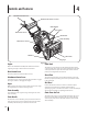
4 Controls and Features Attachment Control Lever Attachment Control Lever Lock Chute Handle Upper Chute Drive Control Lever Chute Knob Chute Assembly Chute Clean-out Tool Skid Shoe Shave Plate Auger Engine Figura 4-1 Refer to the FLEX™ Base Unit Operator’s Manual for details regarding all engine-related controls and features. Drive Control Lever This lever propels the entire machine forward.
5 Operation Starting The Engine 3. Refer to the FLEX™ Power Base’s operator’s manual for engine starting and operating instructions. Once the top mount is engaged (1), and with both hands on the handle grips, tip the unit backwards somewhat swiftly to engage the bottom mounts (2). See Figure 5-3. Couple Snow Thrower Attachment with Power Base 1. With the kickstand UP on the FLEX™ Power Base, as shown in Figure 5-1, roll it over to the snow thrower attachment.
To Engage Drive 1. To engage the drive, squeeze the Drive Control Lever completely up against the upper handle to engage the wheels. To stop the forward motion, release the drive control. Note: This Drive Control Lever is a variable speed drive control. Pulling the drive lever all the way in will give the operator full speed, however full speed should not be achieved for some operations, such as during snow throwing. To Engage Augers 2. Shut off engine as instructed in the engine manual. 3.
6 Maintenance & Adjustments Maintenance Adjusting the Auger Drive Cable General Recommendations After periods of extended use, and during the break-in period, it may be necessary to adjust the auger drive cable. Follow these simple steps to adjust the auger drive cable: • Always observe safety rules when performing any type of maintenance. • The warranty on this snow thrower does not cover items that have been subjected to operator abuse or negligence.
Shave Plate and Skid Shoes Off-Season Storage The shave plate and skid shoes on the bottom of the snow thrower are subject to wear. These should be checked periodically and replaced when necessary. If the snow thrower attachment will not be used for 30 days or longer, or if it is the end of the snow season when the last possibility of snow is gone, the equipment needs to be stored properly. Follow storage instructions below to ensure top performance from the snow thrower for many more years.
7 Service Augers Replacing the Auger Belt The augers are secured to the spiral shaft with four shear pins and cotter pins. If you hit a foreign object or ice jam, the snow thrower is designed so that the pins may shear. 2. Uncouple the FLEX™ Snow Thrower attachment from the FLEX™ Base Unit by deploying the kickstand and tipping the base unit forward. Carefully move the base unit backwards and away from the snow thrower attachment. 3. Park the FLEX™ Base Unit in a safe and stable location. 4.
4. Note: When reinstalling the new belt, be sure that it routes INSIDE of the idler pulley as shown in 1 of Figure 7-6. Carefully tip the FLEX™ Snow Thrower Attachment forward onto the front of the auger housing as shown. Use the mounting handle called out in Figure 7-4 to tip this unit forward. NEVER use the chute handle to either tip this unit forward, for lifting or any other reason other than rotating the discharge chute left or right. Mounting Handle 1 2 Figure 7-6 8. Figure 7-4 5.
8 Troubleshooting Problem Cause Remedy Excessive vibration or noise when the Attachment Control Lever is applied. 1. One or more of the clutch bumpers is missing or worn. 1. Replace the three clutch bumpers with replacement kit part no. 753-08457. 2. Loose parts or damaged auger. 2. Stop engine immediately and disconnect spark plug wire. Check for possible damage. Tighten all bolts and nuts. Repair as needed. If the problem persists, take unit to an authorized service dealer.
9 Replacement Parts Component Part Number and Description 954-05071 Auger Drive Belt 738-04124A 714-04040 Shear Pin, 1.50 Bow-tie Cotter Pin 784-5580 Skid Shoe, Standard (steel) 931-2643 Chute Clean-out Tool 790-00121 Shave Plate 753-08457 Clutch Bumper Kit (6) Phone (800) 828-5500 to order replacement parts or a complete Parts Manual (have your full model number and serial number ready). Parts Manual downloads are also available free of charge at www.troybilt.com.
Notes 10 19
Section 10 — Notes
Section 10 — Notes 21
LIMITED WARRANTY FOR FLEX ATTACHMENT PRODUCT The limited warranty set forth herein is given by Troy-Bilt LLC to the Initial Purchaser (as defined herein) with respect to a new Troy-Bilt-branded FLEX attachment product consisting of one of the following four (4) attachments to the FLEX Power Base (referred to hereafter as the “Attachment”): (i) wide area mower, (ii) snow-thrower, (iii) pressure washer or (iv) leaf blower.
1 Al propietario Gracias Gracias por comprar el Accesorio quitanieve FLEX™ Troy-Bilt. El mismo ha sido cuidadosamente diseñado para brindar excelente rendimiento si se lo opera y mantiene correctamente. Nos reservamos el derecho de modificar las especificaciones de los productos, diseños y equipos sin previo aviso y sin generar responsabilidad por obligaciones de ningún tipo. Por favor lea todo este manual antes de hacer funcionar el equipo.
2 Importantes medidas de seguridad ¡ADVERTENCIA! La presencia de este símbolo indica que se trata de instrucciones de seguridad importantes que se deben respetar para evitar poner en peligro su seguridad personal y/o material y la de otras personas. Lea y cumpla todas las instrucciones de este manual antes de intentar operar esta máquina. Si no respeta estas instrucciones puede provocar lesiones personales. Cuando vea este símbolo.
Manejo seguro de la gasolina 6. No utilice la máquina bajo la influencia de alcohol o drogas. Para evitar lesiones personales o daños materiales tenga mucho cuidado al manipular la gasolina. La gasolina es sumamente inflamable y sus vapores pueden causar explosiones. Si se derrama gasolina encima o sobre la ropa se puede lesionar gravemente ya que se puede encender. Lávese la piel y cámbiese de ropa de inmediato. 7. El silenciador y el motor se calientan y pueden causar quemaduras. No los toque.
Despeje de un canal de descarga obstruido El contacto de las manos con el impulsor rotatorio que está dentro del canal de descarga es la causa más común de lesiones asociadas con las máquinas quitanieve. Nunca use las manos para limpiar el canal de descarga. Para despejar el canal: 1. ¡APAGUE EL MOTOR! 2. Espere 10 segundos para estar seguro de que las cuchillas del motor han dejado de rotar. 3. Utilice siempre una herramienta de limpieza, no use las manos. Mantenimiento y almacenamiento 26 1.
Símbolos de seguridad En esta página se presentan y describen los símbolos de seguridad que en este producto puede tener. Lea, entienda y siga todas las instrucciones incluidas en la máquina antes de intentar armarla y hacerla funcionar. Símbolo Descripción LEA LOS MANUALES DEL OPERADOR Lea, entienda y siga todas las instrucciones incluidas en los manuales antes de intentar armarla y hacerla funcionar. ADVERTENCIA— BARRENA GIRATORIA Evite lesiones por la barrena giratoria.
3 Montaje y Configuración Montaje Instalación del canal de descarga Con el presente accesorio se incluyó un canal de descarga, un resorte de alambre y una banda para canal. Ensámblelos ahora, para lo que debe instalar el canal de descarga en el accesorio quitanieve siguiendo estos pasos: 1. Instale el resorte de alambre en la abertura de descarga del accesorio quitanieve para lo cual debe insertar ambos extremos en las ranuras provistas.
5. Sujete la banda para el canal al canal alineando primero las dos uniones de ajuste a presión y oprimiendo los dos extremos (1 y 2) para unirlos como se indica. Asegúrese de que las dos lengüetas de los extremos queden enganchadas, como se indica en el recuadro superior izquierdo de la Figura 3-5. Si se ensambla correctamente, la banda para el canal debe quedar como se muestra en el recuadro superior derecho de la Figura 3-5.
Canal de descarga Pasadores de cuchilla La posición del canal de descarga superior se puede ajustar de manera de controlar la distancia a la que se arrojará la nieve descargada y la dirección en que será descargada. Siga estos pasos para ajustar el canal de descarga: El accesorio quitanieve trae un par de pasadores de cuchilla de la barrena y pasadores de chaveta con unión curva de reemplazo. Consulte la Figura 3-9. Almacénelos en un lugar seguro hasta que sean necesarios. 1.
4 Controles y Características Palanca de control del accesorio Bloqueo de la palanca de control del accesorio Manija del canal Canal superior Palanca de control de la transmisión Perilla del canal Conjunto del canal Herramienta de limpieza del canal Zapata antideslizante Placa de raspado Barrena Motor Figura 4-1 Consulte el manual del operador de la unidad de base FLEX™ para obtener información sobre todos los controles y las características relacionados con el motor.
5 Funcionamiento Encendido del motor 3. Consulte el manual del operador de la base de potencia FLEX™ para obtener las instrucciones para el arranque y el funcionamiento del motor. Una vez que se engancha el montaje superior (1), y con ambas manos en las empuñaduras de las manijas, incline suavemente la unidad hacia atrás para enganchar los montajes inferiores (2). Consulte la Figura 5-3. Acople el accesorio quitanieve a la base de potencia 1.
Procedimiento para engranar la transmisión 1. 1. Para activar la transmisión, apriete la palanca de control de la transmisión completamente contra la manija de control superior para engranar las ruedas. Para detener la marcha hacia adelante, suelte el control de la transmisión. Suelte tanto la palanca de control del accesorio como la palanca de control de la transmisión. 2. Apague el motor como se indica en el manual del motor. 3.
6 Mantenimiento y Ajustes Mantenimiento Ajuste del cable de transmisión de la barrena Recomendaciones generales Después de períodos de uso prolongado y durante el período de descanso, puede ser necesario ajustar el cable de transmisión de la barrena. Siga estos simples pasos para ajustar dicho cable: • Respete siempre las reglas de seguridad cuando realice cualquier tipo de mantenimiento.
Placa de raspado y zapatas antideslizantes Almacenamiento fuera de temporada La placa de raspado y las zapatas antideslizantes ubicadas en la base de la máquina quitanieve están sujetas a desgaste. Debe controlarlas periódicamente y reemplazarlas cuando sea necesario. Si no se va a utilizar el accesorio quitanieve durante 30 días o más, o si es el final de la temporada de nieve y ya no existe posibilidad de que nieve, es necesario almacenar el equipo de manera adecuada.
7 Servicio Barrenas Cambio de la correa de la barrena Las barrenas están ajustadas al eje espiral con cuatro pasadores de cuchilla y pasadores de chaveta. La máquina quitanieve está diseñada de manera que los pasadores se quiebran si golpea un objeto extraño o una barra de hielo. 2. Desacople el accesorio quitanieve FLEX™ de la unidad base FLEX™ usando el soporte e inclinando la unidad base hacia adelante. Mueva con cuidado la unidad base hacia atrás alejándola del accesorio quitanieve.
4. Nota: Al reinstalar la nueva correa, asegúrese de que pase Incline con cuidado el accesorio quitanieve FLEX™ hacia adelante sobre el frente de la caja de la barrena como se indica. Use la manija de montaje que se indicó en la Figura 7-4 para inclinar esta unidad hacia adelante. NUNCA use la manija del canal para inclinar esta unidad hacia adelante, para levantarla ni para ninguna otra función que no sea girar el canal de descarga a la izquierda o la derecha.
8 Solución De Problemas 38 Problema Causa Remedio La vibración excesiva o ruido cuando se aplica el Anexo palanca de control. 1. Uno o más de los topes de embrague falta o desgastado. 1. Vuelva a colocar los tres topes de embrague con el reemplazo kit ref. 753 a 08.457. 2. Las partes flojas o la barrena está dañada. 2. Detenga el motor de inmediato y desconecte el cable de la bujía. Compruebe por los posibles daños. Apriete todos los tornillos y tuercas. Repare según sea necesario.
9 Piezas de reemplazo Componente Número de pieza y Descripción 954-05071 Auger correa de transmisión 738-04124A 714-04040 Shear Pin, 1.50 Pajarita Chaveta 784-5580 Zapato Skid, Standard (acero) 931-2643 salida Herramienta de limpieza del canal de 790-00121 Placa Shave 753-08457 Pegatina Kit de embrague (6) Teléfono (800) 828-5500 para solicitar piezas de reemplazo o un Manual de Repuestos completo (tenga el número de modelo y número de serie).
GARANTÍA LIMITADA PARA EL ACCESORIO FLEX La garantía limitada que se estable en el presente documento es otorgada por Troy-Bilt LLC al comprador inicial (como se define en este documento) en relación con el nuevo accesorio FLEX Troy-Bilt que está integrado por uno de los siguientes cuatro (4) accesorios de la base de potencia FLEX (identificado en adelante como el "Accesorio"): (i) cortadora de césped con capacidad para superficies amplias, (ii) máquina quitanieve, (iii) lavadora a presión o (iv) soplador d