
Product Manual


7
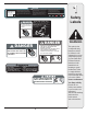
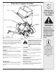
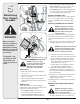
Figure 4
3
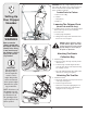
Setting Up
Your Chipper
Shredder
Know Your Chipper Shredder
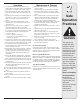
WARNING
Never operate the
chipper shredder with
the chipper chute in the
raised position. Use the
spring latch to lower
the chipper chute into
the operating position
before starting the
engine.
IMPORTANT
Never place branches
with a diameter greater
than 1/2-inch in the
hopper. Doing so
can result in serious
damage to your unit’s
shredder blade, flails or
impeller.
Now that you have set up your chipper shredder for
operation, get aquainted with its controls and fea-
tures. These are described below and illustrated on
this page. This knowledge will allow you to use your
new equipment to its fullest potential.
Chipper Chute
Branches up to 3” in diameter may be fed into the
chipper chute for chipping. See Figure 4.
Hopper
Leaves, twigs and branches up to 1/2-inch in diam-
eter may be placed into the hopper for shredding.
See Figure 4.
IMPORTANT: Never place branches with a diameter
greater than 1/2-inch in the hopper. Doing so can result
in serious damage to your unit’s shredder blade, flails or
impeller.
Spring Latch
The spring latch is located on the top of the hopper.
It is used to release or lock the chipper chute in a
raised position for storage or for transporting. See
Figure 4.
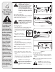
WARNING: Never operate the chipper
shredder with the chipper chute in the
raised position. Use the spring latch
to lower the chipper chute into the
operating position before starting the
engine.
Lock Rod
The lock rod is located on the chipper chute sup-
port. It is used to release or lock the chipper chute
in a lowered position for operation. See Figure 4.
Tow Bar
Use the tow bar to tow the chipper shredder behind
a tractor to a job site. See Figure 4.
Handle
Use the handle when manually transporting the
chipper shredder. See Figure 4.
Starter Handle
The starter handle is located on the engine. Pull the
starter handle to start engine. See Figure 4.
Engine Controls
See the Briggs & Stratton Owner/Operator manual
packed with your unit for the location and function
of the controls on the engine.
Model 24A-424G766 Shown