Safe Operation Practices • Set-Up • Operation • Maintenance • Service • Troubleshooting • Warranty Operator’s Manual Two-Stage Snow Thrower — Storm Tracker 2690XP WARNING READ AND FOLLOW ALL SAFETY RULES AND INSTRUCTIONS IN THIS MANUAL BEFORE ATTEMPTING TO OPERATE THIS MACHINE. FAILURE TO COMPLY WITH THESE INSTRUCTIONS MAY RESULT IN PERSONAL INJURY. TROY-BILT LLC, P.O. BOX 361131 CLEVELAND, OHIO 44136-0019 Printed In USA Form No.
1 To The Owner Thank You Thank you for purchasing a Troy-Bilt Snow Thrower. It was carefully engineered to provide excellent performance when properly operated and maintained. Please read this entire manual prior to operating the equipment. It instructs you how to safely and easily set up, operate and maintain your machine. Please be sure that you, and any other persons who will operate the machine, carefully follow the recommended safety practices at all times.
Important Safe Operation Practices 2 WARNING! This symbol points out important safety instructions which, if not followed, could endanger the personal safety and/or property of yourself and others. Read and follow all instructions in this manual before attempting to operate this machine. Failure to comply with these instructions may result in personal injury. When you see this symbol.
Safe Handling of Gasoline 5. To avoid personal injury or property damage use extreme care in handling gasoline. Gasoline is extremely flammable and the vapors are explosive. Serious personal injury can occur when gasoline is spilled on yourself or your clothes which can ignite. Wash your skin and change clothes immediately. Never run an engine indoors or in a poorly ventilated area. Engine exhaust contains carbon monoxide, an odorless and deadly gas. 6.
Clearing a Clogged Discharge Chute Hand contact with the rotating impeller inside the discharge chute is the most common cause of injury associated with snow throwers. Never use your hand to clean out the discharge chute. To clear the chute: 1. SHUT THE ENGINE OFF! 2. Wait 10 seconds to be sure the impeller blades have stopped rotating. 3. Always use a clean-out tool, not your hands. Maintenance & Storage 1. Never tamper with safety devices. Check their proper operation regularly.
Safety Symbols This page depicts and describes safety symbols that may appear on this product. Read, understand, and follow all instructions on the machine before attempting to assemble and operate. Symbol Description READ THE OPERATOR’S MANUAL(S) Read, understand, and follow all instructions in the manual(s) before attempting to assemble and operate WARNING— ROTATING BLADES Keep hands out of inlet and discharge openings while machine is running.
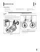
3 Assembly & Set-Up Contents of Carton • One Snow Thrower • Replacement Auger Shear Pins • One Chute Control Rod • One Chute Assembly • One Product Registration Card • One Snow Thrower Operator’s Manual • One Engine Operator’s Manual NOTE: Make certain the cables are seated properly in the roller guides. See Figure 3-2. Assembly Handle 1. Place the shift lever in the Forward-6 position. 2.
Chute Assembly 1. 3. Remove cotter pin, wing nut and hex screw from chute control head. Remove clevis pin and bow-tie cotter pin from chute support bracket. See Figure 3-3. Figure 3-3 2. Insert the round end of the chute control rod into the chute control head. Push rod as far into chute control head as possible, keeping the holes in the rod pointing upward. See Figure 3-4. Place chute onto chute base and ensure chute control rod is positioned under the handle panel.
5. NOTE: The hole furthest from the chute control head is used to achieve further engagement of the chute control rod into the coupler if required. Refer to the Maintenance & Adjustments section for Chute Control Rod adjustment. The hole closest to the chute control head is used for manual movement of the chute assembly if required. Refer to the Controls & Features section. Insert the other end of the chute control rod into the coupler below the handle panel.
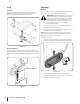
Set-Up Adjustments Shear Pins Skid Shoes Replacement auger shear pins and bow tie cotter pins are included with your snow thrower. Store them in your snow thrower’s dash panel until needed. See Figure 3-10. The snow thrower skid shoes are adjusted at the factory. Adjust them, if desired, prior to operating the snow thrower. CAUTION: Always place the Track Lock Lever in the Gravel position before operating the snow thrower on gravel surfaces.
Auger Control WARNING! Prior to operating your snow thrower, carefully read and follow all instructions below. Perform all adjustments to verify your snow thrower is operating safely and properly. Check the adjustment of the auger control as follows: 1. When the auger control is released and in the disengaged “up” position, the cable should have very little slack. It should NOT be tight. 2. In a well-ventilated area, start the snow thrower engine. Refer to Engine Operator’s Manual. 3.
4 Controls and Features Electric Chute Directional Control Drive Control Shift Lever Auger Control Headlight Heated Grips Track Lock Lever Steering Trigger Control Chute Assembly Chute Clean Out Tool Augers Manual Chute Directional Control Skid Shoe Figure 4-1 Shift Lever Skid Shoes The shift lever is located in the right side of the handle panel and is used to determine ground speed and direction of travel. Forward Position the skid shoes based on surface conditions.
Auger Control Steering Trigger Controls The auger control is located on the left handle. Squeeze the control grip against the handle to engage the augers and start snow throwing action. Release to stop. Drive Control / Auger Clutch Lock The left and right wheel steering trigger controls are located on the underside of the handles. • Squeeze the right control to turn right. • Squeeze the left control to turn left.
Manual Chute Directional Control Track Lock Lever Proceed as follows to utilize the manual chute directional control: The track lock lever is located on the right side of the snow thrower and is used to select the position of the auger housing and the method of track operation. Move the lever to the right, then forward or rearward to one of the four positions. 1. Remove the cotter pin from either of the holes furthest from the chute assembly on the chute rotation assembly. 2.
5 Operation Starting and Stopping the Engine Replacing Shear Pins Refer to the Engine Operator’s Manual packed with your snow thrower for instructions on starting and stopping the engine. The augers are secured to the spiral shaft with shear pins and bow-tie cotter pins. If the auger should strike a foreign object or ice jam, the snow thrower is designed so that the pins may shear. If the augers will not turn, check to see if the pins have sheared. See Figure 5-2. To Engage Track Drive 1.
6 Maintenance & Adjustments Maintenance Lubrication Engine Gear Shaft Refer to the Engine Operator’s Manual. The gear (hex) shaft should be lubricated at least once a season or after every twenty-five (25) hours of operation. Shave Plate and Skid Shoes 1. Allow the engine to run until it is out of fuel. 2. Carefully pivot the snow thrower up and forward so that it rests on the auger housing. NOTE: Deluxe skid shoes (on select models) have two wear edges.
Drive Control When the drive control is released and in the disengaged “up” position, the cable should have very little slack. It should NOT be tight. NOTE: If excessive slack is present in the drive cable or if the snow thrower’s drive is disengaging intermittently during operation, the cable may be in need of adjustment. Check the adjustment of the drive control as follows: Figure 6-3 1. With the drive control released, push the snow thrower gently forward. The unit should roll freely. 2.
Auger Control Continuous Tracks Refer to the Assembly and Set-up section for instructions on adjusting the auger control cable. The snow thrower is equipped with an auto-tensioner on both the left and right sides. The system is designed to maintain constant tension on both tracks. However, if the snow thrower fails to propel itself because the track wheel is “jumping” drive lugs, the tracks are too loose and are in need of adjustment. See an authorized Service Dealer to have the tracks properly adjusted.
7 Service Belt Replacement 3. Roll the auger belt off the engine pulley. See Figure 7-2. Auger Belt To remove and replace your snow thrower’s auger belt, proceed as follows: 1. Allow the engine to run until it is out of fuel. Do not attempt to pour fuel from the engine. Remove the key to avoid unintended starting. 2. Remove the plastic belt cover on the front of the engine by removing the two self-tapping screws. See Figure 7-1. Figure 7-2 4.
6. Loosen and remove the shoulder bolt which acts as a belt keeper. See Figure 7-4. 8. Replace the auger belt by following instructions in reverse order. NOTE: Do not forget to reinstall the shoulder bolt and reconnect the spring to the frame after installing a replacement auger belt. 9. After replacing the auger belt, perform the Auger Control test on page 11 to verify the belt is adjusted correctly.
8 Troubleshooting Problem Engine fails to start Cause Remedy 1. Fuel tank empty, or stale fuel. 1. Fill tank with clean, fresh gasoline. Fuel becomes stale after thirty days. 2. Blocked fuel line. 2. Clean the fuel line. 3. Choke not in the RUN position. 3. Move choke control to RUN position 4. Faulty spark plug. 4. Clean, adjust gap or replace. 5. Key not in ignition switch on engine. 5. Insert the key fully into the switch. 6. Spark plug wire disconnected. 6. Connect spark plug wire. 7.
9 Replacement Parts Component Part Number and Description 954-04050 754-0356 Auger Drive Belt Track Drive Belt 684-04153C 735-04054 Friction Wheel Assembly Friction Wheel Rubber 925-1629 Lamp, 12V 738-04124A 714-04040 Shear Pin, 1.
10 Attachments & Accessories The following attachments and accessories are available for your Troy-Bilt snow thrower. Phone (800) 828-5500 for information regarding compatibility, price and availability (have your full model number and serial number ready).
MANUFACTURER’S LIMITED WARRANTY FOR The limited warranty set forth below is given by Troy-Bilt LLC with respect to new merchandise purchased and used in the United States and/or its territories and possessions, and by MTD Products Limited with respect to new merchandise purchased and used in Canada and/or its territories and possessions (either entity respectively, “Troy-Bilt”). b.
Medidas importantes de seguridad • Configuración • Funcionamiento • Mantenimiento • Servicio • Solución de problemas • Garantía Manual del Operador Máquina quitanieve de dos etapas — Storm Tracker 2690XP ADVERTENCIA LEA Y RESPETE TODAS LAS NORMAS DE SEGURIDAD E INSTRUCCIONES INCLUIDAS EN ESTE MANUAL ANTES DE PONER EN FUNCIONAMIENTO ESTA MÁQUINA. SI NO RESPETA ESTAS INSTRUCCIONES PUEDE PROVOCAR LESIONES PERSONALES. TROY-BILT LLC, P.O.
1 Al propietario Gracias Gracias por comprar una máquina quitanieve de Troy-Bilt LLC. La misma ha sido diseñada cuidadosamente para brindar excelente rendimiento si se la opera y mantiene correctamente. Por favor lea todo este manual antes de operar el equipo. Le indica cómo configurar, operar y mantener la máquina con seguridad y fácilmente. Por favor cerciórese de que usted o cualquier otra persona que opere la máquina siga cuidadosamente y en todo momento las prácticas de seguridad recomendadas.
Medidas Importantes de Seguridad 2 ¡ADVERTENCIA! La presencia de este símbolo indica que se trata de instrucciones importantes de seguridad que se deben respetar para evitar poner en peligro su seguridad personal y/o material y la de otras personas. Lea y siga todas las instrucciones de este manual antes de poner en funcionamiento esta máquina. Si no respeta estas instrucciones puede provocar lesiones personales. Cuando vea este símbolo.
6. Nunca intente realizar ajustes mientras el motor está en marcha excepto en los casos específicamente recomendados en el manual del operador. 7. Deje que el motor y la máquina se adapten a la temperatura exterior antes de comenzar a sacar la nieve. Manejo seguro de la gasolina Para evitar lesiones personales o daños materiales tenga mucho cuidado cuando trabaje con gasolina. La gasolina es sumamente inflamable y sus vapores pueden causar explosiones.
20. 21. Para encender el motor, jale de la cuerda lentamente hasta que sienta resistencia, luego jale rápidamente. El repliegue rápido de la cuerda de arranque (tensión de retroceso) le jalará la mano y el brazo hacia el motor más rápido de lo que usted puede soltar. El resultado pueden ser huesos rotos, fracturas, hematomas o esguinces. Si se presentan situaciones que no están previstas en este manual, sea cuidadoso y use el sentido común.
Símbolos de Seguridad Esta página describe los símbolos y figuras de seguridad internacionales que pueden aparecer en este producto. Lea el manual del operador para obtener la información terminada sobre seguridad, reunirse, operación y mantenimiento y reparación. Símbolo Descripción LEA EL MANUAL DEL OPERADOR (S) Lea, entienda, y siga todas las instrucciones en el manual (es) antes de intentar reunirse y funcionar.
3 Montaje y Configuración Contenido de la caja de cartón • Una máquina quitanieve • Dos pasadores de cuchilla de barrena de repuesto • Una varilla de control del canal • Un conjunto de canal • Una tarjeta para registrar el producto • Un Manual del Operador de la Máquina Quitanieve • Un Manual del Motor NOTA: Asegúrese de que los cables estén bien asentados en las guías de los rodillos. Consulte la Figura 3-2. Montaje Manija 1. Coloque la palanca de cambios en la posición de avance (F) 6. 2.
Conjunto del canal 1. 3. Retire el pasador de chaveta, la tuerca de mariposa y el tornillo hexagonal del cabezal de control del canal. Extraiga el pasador de horquilla y el pasador de chaveta con unión curva de la ménsula de soporte del canal. Consulte la Figura 3-3. Figura 3-3 2. Inserte el extremo redondeado de la varilla de control del canal en el cabezal de control del canal.
5. NOTA: El orificio más alejado del cabezal de control del canal se utiliza para insertar más la varilla de control del canal en el acoplador si resulta necesario. Consulte la sección de Mantenimiento y Ajustes para saber cómo ajustar la varilla de control del canal. El orificio más cercano al cabezal de control del canal se utiliza para mover manualmente el conjunto del canal si resulta necesario. Consulte la sección de Controles y Características.
Configuración Ajustes Pasadores de cuchilla Zapatas antideslizantes Su máquina quitanieve trae un par de pasadores de cuchilla de la barrena y pasadores de chaveta con unión curva de reemplazo. Guárdelos en el panel de instrumentos de la máquina hasta que los necesite. Consulte la Figura 3-10. Las zapatas antideslizantes de la máquina quitanieve se ajustan en fábrica para el envío. Si lo desea, puede ajustarlas hacia abajo antes de hacer funcionar la máquina quitanieve.
Control de la barrena ¡ADVERTENCIA! Antes de operar su máquina quitanieve, lea atentamente y cumpla todas las instrucciones que aparecen a continuación. Realice todos los ajustes para verificar que la máquina está operando con seguridad y correctamente. Compruebe el ajuste del control de la barrena de la siguiente forma: 1. Cuando se suelta el control de la barrena y está en posición desengranada arriba, el cable debe tener muy poco juego. NO debe estar tenso. 2.
4 Controles y Características Control direccional del canal eléctrico Control de la transmisión Palanca de cambios Control de la barrena Faro delantero Agarre térmico Palanca de traba de las orugas Mando de la dirección Conjunto del canal Herramienta de limpieza del canal Barrenas Control direccional del canal manual Zapata de deslizamiento Figura 4-1 Los controles y características de la máquina quitanieve se describen a continuación y se ilustran en la Figura 4-1.
Control de la barrena Mandos de la dirección CONTROL DE LA BARRENA MANDOS DE LA DIRECCIÓN TODO LISTO DETENCIÓN El control de la barrena está ubicado en la manija izquierda. Apriete la empuñadura de control contra la manija para engranar las barrenas y empiece a quitar nieve. Suelte para que se detenga. Control de transmisión / Traba del embrague de la barrena CONTROL DE TRANSMISIÓN Los controles de la dirección del volante izquierdo y derecho se ubican en la parte inferior de las manijas.
Control direccional del canal manual Palanca de traba de las orugas Para utilizar el control direccional del canal manual, proceda de la siguiente manera: La palanca de traba de las orugas está situada en el lado derecho de la máquina quitanieve, y se utiliza para seleccionar la posición de la caja de la barrena y el método de operación de las orugas. Mueva la palanca a la derecha, y luego hacia delante o hacia atrás, a una de las cuatro posiciones. 1.
5 Funcionamiento Arranque y detención del motor Reemplazo de los pasadores de cuchilla Consulte el manual de operación del motor embalado con su máquina quitanieve para ver las instrucciones sobre cómo arrancar y detener el motor. Las barrenas están ajustadas al eje espiral con pasadores de cuchilla y pasadores de chaveta con unión curva. La máquina quitanieve ha sido diseñada para que los pasadores se quiebren si la barrena golpeara un objeto extraño o un trozo de hielo.
6 Mantenimiento y Ajustes Mantenimiento Lubricación Motor Eje de engranaje Consulte el manual del operador del motor. El eje de engranaje (hexagonal) se debe lubricar al menos una vez por temporada o después de cada lapso de 25 horas de operación. Placa de raspado y zapatas antideslizantes La placa de raspado y las zapatas antideslizantes ubicadas en la base de la máquina quitanieve están sujetas a desgaste. Debe controlarlas periódicamente y reemplazarlas cuando sea necesario.
Control de la transmisión Cuando se suelta el control de la transmisión y está en posición desenganchada arriba, el cable debe tener muy poco juego. NO debe estar tenso. NOTA: Si el cable de transmisión tiene demasiado juego o si la transmisión de la máquina quitanieve se desengrana intermitentemente durante la operación, es posible que deba ajustar el cable. Compruebe el ajuste del control de la transmisión de la siguiente forma: 1.
Control de la barrena Orugas continuas Consulte la sección Montaje y Configuración para ver las instrucciones de ajuste del cable de control de la barrena. La máquina quitanieve está equipada con un autotensionador a ambos lados, izquierdo y derecho. El sistema está diseñado para mantener la tensión constante en ambas orugas. Sin embargo, si la máquina quitanieve no se impulsa porque la rueda de las orugas está "saltando" espigas de transmisión, las orugas están demasiado flojas y se deben ajustar.
7 Servicio Cambio de correa 3. Correa de barrena Saque la correa de la barrena de la polea del motor. Consulte la Figura 7-2. Para retirar y reemplazar la correa de la barrena de su máquina quitanieve, proceda como se indica a continuación: 1. Deje el motor en marcha hasta que se acabe el combustible. No intente verter combustible del motor. Saque la llave para evitar el arranque accidental. 2.
6. Afloje y retire el perno con reborde que actúa como guardacorrea. Consulte la Figura 7-4. 8. Reemplace la correa de la barrena siguiendo las instrucciones en orden inverso. NOTA: No olvide volver a instalar el perno con reborde y volver a conectar el resorte al marco tras instalar la correa de la barrena de repuesto. 9. Después de colocar la correa de la barrena, realice la prueba de control de la barrena que se describe en la página para verificar que la correa esté correctamente ajustada.
8 Solución de Problemas Problema El motor no arranca Causa Solución 1. El depósito de combustible está vacío o el combustible se ha echado a perder. 1. Llene el tanque con gasolina limpia y nueva. El combustible envejece transcurridos treinta días. 2. La línea de combustible está tapada. 2. Limpie la línea del combustible. 3. La palanca de obturación no está en la posición RUN (marcha). 3. Mueva la palanca del cebador a la posición RUN (marcha). 4. La bujía no funciona correctamente. 4.
Notas 46 9
Section 9 — Notas 47
GARANTÍA LIMITADA DEL FABRICANTE PARA La siguiente garantía limitada es otorgada por Troy-Bilt LLC con respecto a nuevos productos adquiridos y utilizados en Estados Unidos y/o sus territorios y posesiones, y por MTD Products Limited con respecto a nuevos productos adquiridos y utilizados en Canadá y/o sus territorios y posesiones (cualquiera de las dos entidades, respectivamente, “Troy-Bilt”). Esta garantía es adicional a la garantía de emisiones aplicables proporcionada con el producto.