Safe Operation Practices • Set-Up • Operation • Maintenance • Service • Troubleshooting • Warranty Operator’s Manual Two-Stage Snow Thrower — Storm 2410, 2620, 2840 & 3090XP WARNING READ AND FOLLOW ALL SAFETY RULES AND INSTRUCTIONS IN THIS MANUAL BEFORE ATTEMPTING TO OPERATE THIS MACHINE. FAILURE TO COMPLY WITH THESE INSTRUCTIONS MAY RESULT IN PERSONAL INJURY. TROY-BILT LLC, P.O. BOX 361131 CLEVELAND, OHIO 44136-0019 Printed In USA Form No.
1 To The Owner Thank You Thank you for purchasing a Troy-Bilt Snow Thrower. It was carefully engineered to provide excellent performance when properly operated and maintained. Please read this entire manual prior to operating the equipment. It instructs you how to safely and easily set up, operate and maintain your machine. Please be sure that you, and any other persons who will operate the machine, carefully follow the recommended safety practices at all times.
Important Safe Operation Practices 2 WARNING! This symbol points out important safety instructions which, if not followed, could endanger the personal safety and/or property of yourself and others. Read and follow all instructions in this manual before attempting to operate this machine. Failure to comply with these instructions may result in personal injury. When you see this symbol.
Safe Handling of Gasoline 5. To avoid personal injury or property damage use extreme care in handling gasoline. Gasoline is extremely flammable and the vapors are explosive. Serious personal injury can occur when gasoline is spilled on yourself or your clothes which can ignite. Wash your skin and change clothes immediately. Never run an engine indoors or in a poorly ventilated area. Engine exhaust contains carbon monoxide, an odorless and deadly gas. 6.
Clearing a Clogged Discharge Chute Hand contact with the rotating impeller inside the discharge chute is the most common cause of injury associated with snow throwers. Never use your hand to clean out the discharge chute. To clear the chute: 1. SHUT THE ENGINE OFF! 2. Wait 10 seconds to be sure the impeller blades have stopped rotating. 3. Always use a clean-out tool, not your hands. Maintenance & Storage 1. Never tamper with safety devices. Check their proper operation regularly.
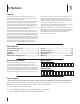
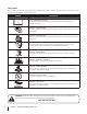
Safety Symbols This page depicts and describes safety symbols that may appear on this product. Read, understand, and follow all instructions on the machine before attempting to assemble and operate. Symbol Description READ THE OPERATOR’S MANUAL(S) Read, understand, and follow all instructions in the manual(s) before attempting to assemble and operate WARNING— ROTATING BLADES Keep hands out of inlet and discharge openings while machine is running.
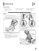
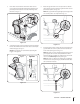
3 Assembly & Set-Up Contents of Carton • One Snow Thrower • Two Replacement Auger Shear Pins • One Chute Assembly (Model 2410) • One Snow Thrower Operator’s Manual • One Product Registration Card • One Chute Control Rod (Models 2620, 2840 and 3090XP) • One Engine Manual Assembly Handle 1. Place the shift lever in the Forward-6 position. 2. Observe the lower rear area of the snow thrower to be sure both cables are aligned with roller guides before pivoting the handle upward. See Fig. 3-1.
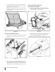
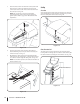
2. Close the flange keepers to secure the chute assembly to the chute base. The flange keepers will click into place when properly secure. See Fig. 3-4. NOTE: If the flange keepers will not easily click into place, use the palm of your hand to apply swift, firm pressure to the back of each. Chute Assembly and Directional Control (Models 2620, 2840 and 3090XP) 1. Remove cotter pin, wing nut and hex screw from chute control head. Remove clevis pin and bow-tie cotter pin from chute support bracket. See Fig.
3. Place chute onto chute base and ensure chute control rod is positioned under the handle panel. Install hex bolt previously removed, but do not secure with wing nut at this time. See Fig. 3-8. 5. Rotate the joystick to the one o’clock position so that the silver indicator arrow on the pinion gear below the control panel faces upward. See Fig. 3-10. NOTE: The joystick will be angled slightly to the right at the one o’clock position. See “Top View” in Fig. 3-9. Figure 3-8 4.
7. Push the chute control rod toward the control panel until the hole in the rod lines up with the hole in the chute control input closest to the chute control head and insert the cotter pin. See Fig. 3-12. NOTE: The second hole is used to achieve further engagement of the chute control rod into the pinion gear if required. Refer to page 19 for Chute Control Rod adjustments. Set-Up Shear Pins A pair of replacement auger shear pins and bow tie cotter pins are included with your snow thrower.
Tire Pressure Warning: Under any circumstance do not exceed manufacturer’s recommended psi. Equal tire pressure should be maintained at all times. Excessive pressure when seating beads may cause tire/rim assembly to burst with force sufficient to cause serious injury. Refer to side wall of tire for recommended pressure. The tires are over-inflated for shipping purposes. Check the tire pressure before operating the snow thrower.
Auger Control Warning! Prior to operating your snow thrower, carefully read and follow all instructions below. Perform all adjustments to verify your snow thrower is operating safely and properly. Check the adjustment of the auger control as follows: 1. When the auger control is released and in the disengaged “up” position, the cable should have very little slack. It should NOT be tight. 2. In a well-ventilated area, start the snow thrower engine. Refer to Engine Operator’s Manual. 3.
4 Controls and Features 4-Way/2-Way Chute Directional Control † Auger Control Drive Control Shift Lever † Heated Grips † Headlight † Steering Trigger Control † Chute Assembly Chute Clean Out Tool Standard Chute Directional Control † Skid Shoe Augers † If Equipped Figure 4-1 Snow thrower controls and features are described below and illustrated in Fig. 4-1. Shift Lever The shift lever is located in the right side of the handle panel and is used to determine ground speed and direction of travel.
Auger Control Standard Chute Directional Control (if so equipped) T The auger control is located on the left handle. Squeeze the control grip against the handle to engage the augers and start snow throwing action. Release to stop. Drive Control / Auger Clutch Lock The chute directional control is located on left side of the snow thrower. To change the direction in which snow is thrown, rotate chute directional control.
4-Way Chute Directional Control (if so equipped) Chute Clean-Out Tool Warning! Never use your hands to clear a clogged chute assembly. Shut off engine and remain behind handles until all moving parts have stopped before unclogging. The chute clean-out tool is conveniently fastened to the rear of the auger housing with a mounting clip.
5 Operation Starting and Stopping the Engine Replacing Shear Pins Refer to the Engine Operator’s Manual packed with your snow thrower for instructions on starting and stopping the engine. The augers are secured to the spiral shaft with shear pins and bow-tie cotter pins. If the auger should strike a foreign object or ice jam, the snow thrower is designed so that the pins may shear. If the augers will not turn, check to see if the pins have sheared. See Fig. 5-2. To Engage Drive 1. 2.
6 Maintenance & Adjustments Maintenance Lubrication Engine Gear Shaft Refer to the Engine Operator’s Manual. The gear (hex) shaft should be lubricated at least once a season or after every twenty-five (25) hours of operation. Shave Plate and Skid Shoes 1. Allow the engine to run until it is out of fuel. 2. Carefully pivot the snow thrower up and forward so that it rests on the auger housing. NOTE: Deluxe skid shoes (on select models) have two wear edges.
Auger Shaft Drive Control At least once a season, remove the shear pins from the auger shaft. Spray lubricant inside the shaft and around the spacers and the flange bearings found at either end of the shaft. See Fig. 6-3. When the drive control is released and in the disengaged “up” position, the cable should have very little slack. It should NOT be tight.
Chute Assembly Chute Bracket Adjustment (Model 2410) Refer to the Assembly and Set-up section for instructions on adjusting the chute assembly. If the spiral at the bottom of the chute directional control is not fully engaging with the chute assembly, the chute bracket can be adjusted. To do so: Skid Shoes Refer to the Assembly and Set-up section for instructions on adjusting the skid shoes. 1. Loosen the two nuts which secure the chute bracket and reposition it slightly. See Fig. 6-7.
7 Service Belt Replacement 4. Carefully pivot the snow thrower up and forward so that it rests on the auger housing. Auger Belt 5. Remove the frame cover from the underside of the snow thrower by removing the self-tapping screws which secure it. See Fig. 7-3. To remove and replace your snow thrower’s auger belt, proceed as follows: 1. Allow the engine to run until it is out of fuel. Do not attempt to pour fuel from the engine. Remove the key to avoid unintended starting. 2.
7. Remove the belt from around the auger pulley, and slip the belt between the support bracket and the auger pulley. See Fig. 7-5. Drive Belt To remove and replace your snow thrower’s drive belt, proceed as follows: 1. To prevent spillage, remove all fuel from tank by running engine until it stops. Do not attempt to pour fuel from the engine. 2. Remove the plastic belt cover on the front of the engine by removing the two self-tapping screws. Refer to Fig. 7-1. 3. Remove the belt as follows (See Fig.
6. Back out the stop bolt to increase the clearance between the friction wheel disc and friction wheel. See Fig. 7-7. Friction Wheel Removal (Models 2410, 2620 & 2840) If the snow thrower fails to drive with the drive control engaged, and performing the drive control cable adjustment fails to correct the problem, the friction wheel may need to be replaced. Follow the instructions below. Examine the friction wheel for signs of wear or cracking and replace if necessary: Stop Bolt 1.
5. Carefully remove the hex nut which secures the hex shaft to the snow thrower frame and lightly tap the shaft’s end to dislodge the ball bearing from the right side of the frame. See Fig. 7-9. 7. Follow the previous steps in reverse order to reassemble components. 8. Perform the Drive Control test on page 18 in the Maintenance and Adjustments section. NOTE: Be careful not to damage the threads on the shaft.
8 Troubleshooting Problem Engine fails to start Remedy 1. Choke not in CHOKE position. 1. Move choke to CHOKE position. 2. Spark plug wire disconnected. 2. Connect wire to spark plug. 3. Fuel tank empty or stale fuel. 3. Fill tank with clean, fresh gasoline. 4. Engine not primed. 4. Prime engine as instructed in the Operation section. 5. Faulty spark plug. 5. Clean, adjust gap, or replace. 6. Key not in ignition on engine. 6. Insert key fully into the switch. 7.
9 Replacement Parts Component Part Number and Description 929-0071A Extension Cord, 110V 954-04050 Auger Drive Belt (Storm 2410 & Storm 2620 with 15” tires) Auger Drive Belt (Storm 2840 & 3090XP & Storm 2620 with 16” tires) Wheel Drive Belt (Storm 2410 & Storm 2620 with 15” tires) Wheel Drive Belt (Storm 2840 & 3090XP & Storm 2620 with 16” tires) 954-04195 954-04260 954-04201A 684-04153 684-04159 935-04054 Friction Wheel Assembly (Storm 2410, 2620 & 2840) Friction Wheel Assembly (Storm 3090XP) Frict
10 Attachments & Accessories The following attachments and accessories are available for your Troy-Bilt snow thrower. Phone (800) 828-5500 for information regarding compatibility, price and availability (have your full model number and serial number ready). Model Number 753-05762A Heated Grips* OEM-390-679 Drift Cutter Kit 490-241-0010 Polymer Skid Shoe Kit OEM-390-995 Snow Thrower Protective Cover 490-241-Y014 Troy-Bilt Snow Thrower Maintenance Kit *Not compatible with Storm 2410.
Notes 11 27
MANUFACTURER’S LIMITED WARRANTY FOR The limited warranty set forth below is given by Troy-Bilt LLC with respect to new merchandise purchased and used in the United States and/or its territories and possessions, and by MTD Products Limited with respect to new merchandise purchased and used in Canada and/ or its territories and possessions (either entity respectively, “TroyBilt”). c. Service completed by someone other than an authorized service dealer.
Medidas importantes de seguridad • Configuración • Funcionamiento • Mantenimiento • Servicio • Solución de problemas • Garantía Manual del operador Máquina quitanieve de dos etapas — Storm 2410, 2620, 2840 & 3090XP ADVERTENCIA LEA Y SIGA TODAS LAS INSTRUCCIONES DE ESTE MANUAL ANTES DE PONER EN FUNCIONAMIENTO ESTA MÁQUINA. SI NO RESPETA ESTAS INSTRUCCIONES PUEDE PROVOCAR LESIONES PERSONALES. TROY-BILT LLC, P.O. BOX 361131 CLEVELAND, OHIO 44136-0019 Impreso en Estados Unidos de América Formulario No.
1 Al propietario Gracias Gracias por comprar una Troy-Bilt máquina quitanieve. La misma ha sido diseñada cuidadosamente para brindar excelente rendimiento si se la opera y mantiene correctamente. las especificaciones de los productos, los diseños y el equipo estándar sin previo aviso y sin generar responsabilidad por obligaciones de ningún tipo. Por favor lea todo este manual antes de operar el equipo. Le indica cómo configurar, operar y mantener la máquina con seguridad y fácilmente.
2 Medidas importantes de seguridad ¡ADVERTENCIA! La presencia de este símbolo indica que se trata de instrucciones importantes de seguridad que se deben respetar para evitar poner en peligro su seguridad personal y/o material y la de otras personas. Lea y siga todas las instrucciones de este manual antes de poner en funcionamiento esta máquina. Si no respeta estas instrucciones puede provocar lesiones personales. Cuando vea este símbolo.
6. Nunca intente realizar ajustes mientras el motor está en marcha excepto en los casos específicamente recomendados en el manual del operador. 7. Deje que el motor y la máquina se adapten a la temperatura exterior antes de comenzar a sacar la nieve. Manejo seguro de la gasolina Para evitar lesiones personales o daños materiales tenga mucho cuidado cuando trabaje con gasolina. La gasolina es sumamente inflamable y sus vapores pueden causar explosiones.
20. 21. Para encender el motor, jale de la cuerda lentamente hasta que sienta resistencia, luego jale rápidamente. El repliegue rápido de la cuerda de arranque (tensión de retroceso) le jalará la mano y el brazo hacia el motor más rápido de lo que usted puede soltar. El resultado pueden ser huesos rotos, fracturas, hematomas o esguinces. Si se presentan situaciones que no están previstas en este manual, sea cuidadoso y use el sentido común.
Símbolos de Seguridad Esta página describe los símbolos y figuras de seguridad internacionales que pueden aparecer en este producto. Lea el manual del operador para obtener la información terminada sobre seguridad, reunirse, operación y mantenimiento y reparación. Símbolo Descripción LEA EL MANUAL DEL OPERADOR (S) Lea, entienda, y siga todas las instrucciones en el manual (es) antes de intentar reunirse y funcionar.
3 Montaje y Configuración Contenido de la caja • Una máquina quitanieve • Dos pasadores de cuchilla de barrena de repuesto • Una tarjeta para registrar el producto • Un Manual del Operador de la Máquina Quitanieve • Varilla hexagonal • Canal de montaje • Un Manual del Motor Montaje Manija 1. Coloque la palanca de cambios en la posición de avance (F) 6. 2.
2. Cierre a los guardas de reborde para asegurar la asamblea de tobogán a la base del tobogán. Los guardas de reborde harán clic en el lugar cuando aseguran apropiadamente. Vea la Fig. 3-4. Montaje del canal (Modelos 2620, 2840, y 3090XP) 1. Retire el pasador de chaveta, la tuerca de mariposa y el tornillo hexagonal del cabezal de control del canal, y el pasador de horquilla y el pasador de chaveta con unión curva de la ménsula de soporte del canal. Vea la Fig. 3-6.
3. Lugar en la tolva tolva de base y garantizar la varilla hexagonal está situado bajo el asa del panel. Instalar el perno hexagonal previamente eliminado, pero no seguro con tuerca de mariposa en este momento. Vea la Fig. 3-8. 5. Nota: La palanca de control girará ligeramente hacia la derecha. Vea “Vista desde arriba” en la Fig. 3-9. Figura 3-8 4. Gire la palanca de control hasta que la flecha indicadora plateada en el engranaje del piñón por debajo del panel de control señale hacia arriba.
7. Empuje la varilla hacia el panel de control hasta que el orificio en la varilla hexagonal se alinee con el orificio en la entrada de control del canal lo más cerca posible del cabezal de control del canal e inserte el pasador de chaveta. Vea la Fig. 3-12. Nota: Para más suave funcionamiento, los cables deben estar a la izquierda de la varilla hexagonal.
Presión de los neumáticos Advertencia: Bajo ninguna circunstancia no excedan del fabricante recomienda psi. La igualdad de la presión de los neumáticos deben mantenerse en todo momento. Cuando la presión excesiva puede causar asientos bolas neumático / llanta de montaje para reventar con la fuerza suficiente para causar un daño grave. Se refieren a los flancos de los neumáticos de la presión recomendada. Los neumáticos son demasiado inflados para propósitos de envío.
3. Inserte la llave en el motor del motor y arranque. Consulte el manual del operador del motor. 7. Control de la barrena Para volver a ajustar el cable de control, afloje la tuerca hexagonal superior en la ménsula del cable de la barrena. Vea la Fig. 3-18. ¡Advertencia! Antes de operar su máquina quitanieve, lea atentamente y cumpla todas las instrucciones que aparecen a continuación. Realice todos los ajustes para verificar que la máquina está operando con seguridad y correctamente.
4 Controles y Características Control del Canal de Dos/Cuatro Direcciones † Control de Transmisión Control de la Barrena Palanca de Cambios † Agarre Termico † Faro Delantero † Control Disparador del Manejo † Montaje del Canal Herramienta de Limpieza del Canal Control direccional del canal † Zapatas Antideslizantes Barrenas † Si está equipado Figura 4-1 Los controles y características de la máquina quitanieve se describen a continuación y se ilustran en la Fig. 4-1.
Control de la barrena Control Direccional del Canal (si está equipado) T El control de la barrena está ubicado en la manija izquierda. Apriete la empuñadura de control contra la manija para engranar las barrenas y empiece a quitar nieve. Suelte para que se detenga. Control de transmisión / Traba del embrague de la barrena El control de transmisión está ubicado en la manija derecha. Oprima la empuñadura de control contra la manija para engranar la rueda de transmisión. Suelte para que se detenga.
Control del canal de dos direcciones (si está equipado) Herramienta de limpieza del canal ¡Advertencia! Nunca use las manos para liberar un montaje de canal tapado. Antes de destaparlo, apague el motor y permanezca detrás de las manijas hasta que todas las partes móviles se hayan detenido. La herramienta de limpieza del canal está ajustada convenientemente a la parte posterior de la caja de la barrena con un pasador de ensamblado.
5 Funcionamiento Encendido del Motor y Detención del Motor Reemplazo de los Pasadores de Cuchilla Consulte el Mantenimiento del Motor para motores embalado con la máquina para ver el Encendido del Motor y Detención del motor. Las barrenas están ajustadas al eje espiral con dos pasadores de cuchilla y pasadores de chaveta. Si la barrena golpeara un objeto extraño o un trozo de hielo, la máquina quitanieve ha sido diseñada para que los pasadores se quiebren.
6 Mantenimiento y Ajustes Mantenimiento Lubricación Motor Eje de engranaje Consulte el Mantenimiento del Motor para motores embalado con la máquina para ver el mantenimiento del motor. El eje de engranaje (hexagonal) se debe lubricar al menos una vez por temporada o tras cada 25 horas de operación. Placa de raspado y zapatas antideslizantes 1. Deje que el motor funcione hasta que se acabe el combustible. 2.
Eje de la barrena 3. Gire el soporte hacia abajo para reducir el juego del cable. Al menos una vez por temporada, quite los pasadores de cuchilla del eje de la barrena. Rocíe lubricante en el interior del eje y alrededor de los separadores y los cojinetes bridados que se encuentran en ambos extremos del eje. Vea la Fig. 6-3. 4. Vuelva a apretar la tuerca hexagonal.
Control de la barrena Ajuste del soporte del canal (Si está equipado) Consulte la sección Montaje y Configuración para ver las instrucciones del ajuste del cable de control de la barrena. Si el espiral en el fondo del control direccional del canal no está enganchando completamente con el montaje del canal , el soporte del canal puede ser ajustado.
7 Servicio Cambio de Correa 4. Gire con cuidado la máquina quitanieve hacia arriba y hacia delante de manera que quede apoyada sobre la caja de la barrena. 5. Saque la cubierta del marco desde debajo de la máquina quitanieve retirando los cuatro tornillos autorroscantes que la aseguran. Vea la Fig. 7-3. Correa de la Barrena Para retirar y reemplazar la correa de la barrena de su máquina quitanieve, proceda como se indica a continuación: 1. Deje que el motor funcione hasta que se acabe el combustible.
7. Retire la correa de alrededor de la polea de la barrena y deslice la misma entre la ménsula de soporte y la polea de la barrena. Vea la Fig. 7-5. 3. Quite la correa como sigue: Vea la Fig. 7-6: a. Saque la correa de la barrena de la polea del motor. b. Use una llave para girar la polea loca hacia la derecha. c. Levante la correa de la barrena para sacarla de la polea del motor. Figura 7-5 8. 9. Para realizar el reensamblado de la correa de la barrena siga las instrucciones en orden inverso.
6. Volver a cabo el perno de tope para aumentar el espacio libre entre el disco de la rueda de fricción y rueda de fricción. Véase la Fig. 7-7. Extracción de la Rueda de Fricción (Storm 2410, 2620 & 2840) Si la máquina quitanieve no se mueve cuando el control de la transmisión está engranado, y si al realizar el ajuste del cable de control de la transmisión el problema no se corrige, es posible que deba reemplazar la rueda de fricción. Siga las instrucciones que aparecen a continuación.
5. Retire con cuidado la tuerca hexagonal y la arandela que sujetan el eje hexagonal al marco de la máquina quitanieve, y golpee suavemente el extremo del eje para desplazar el cojinete de bolas del lado derecho del marco. Vea la Fig. 7-9. NOTA: Tenga cuidado de no dañar las roscas del eje. 7. Para reensamblar los componentes siga los pasos anteriores en orden inverso. 8. Realizar la prueba de la unidad de control en la página 46 en la sección Mantenimiento y Ajustes.
8 Solución de Problemas Problema El motor no arranca Solución 1. El control del cebador no está en la posición CHOKE (encendido). 1. Ponga el control del cebador en la posición CHOKE (encendido). 2. Se ha desconectado el cable de la bujía. 2. Conecte el cable a la bujía. 3. El depósito de combustible está vacío o el combustible se ha echado a perder. 3. Llene el tanque con gasolina limpia y fresca. 4. El motor no está cebado. 4. Cebe el motor tal como se explicó en la sección Funcionamiento. 5.
Problema La unidad no se autoimpulsa La unidad no descarga la nieve Chute no girar 180 grados Causa Solución 1. El cable del control de transmisión necesita un ajuste. 1. Ajuste el cable del control de transmisión. Consulte la sección Mantenimiento y Ajustes. 2. La correa de transmisión está floja o dañada. 2. Reemplace la correa de transmisión. Consulte la sección de Servicio. 3. La fricción de la rueda desgastada. 3. Vuelva a colocar la rueda de fricción. Consulte la sección de servicio. 1.
9 Piezas de Reemplazo Componente Número de pieza y Descripción 929-0071A Cordón prolongador, 110V 954-04050 Correa de transmisión de la barrena (Storm 2410 & 2620 con 15” neumáticos) Correa de transmisión de la barrena (Storm 2840 & 3090XP & Storm 2620 con 16” neumáticos) Correa de transmisión de la rueda (Storm 2410 & 2620 con 15” neumáticos) Correa de transmisión de la rueda (Storm 2840 & 3090XP & Storm 2620 con 16” neumáticos) 954-04195 954-04260 954-04201A 684-04153 684-04159 935-04054 Montaje d
10 Aditamentos y Accesorios Los siguientes aditamentos y accesorios son compatibles con el máquina quitanieve. Llame (800) 828-5500 para la información con respecto a la compatibilidad, el precio y la disponibilidad (tener su número de modelo completo y número de serie).
GARANTÍA LIMITADA DEL FABRICANTE PARA La siguiente garantía limitada es otorgada por Troy-Bilt LLC con respecto a nuevos productos adquiridos y utilizados en Estados Unidos y/o sus territorios y posesiones, y por MTD Products Limited con respecto a nuevos productos adquiridos y utilizados en Canadá y/o sus territorios y posesiones (cualquiera de las dos entidades, respectivamente, “Troy-Bilt”).