Safe Operation Practices • Set-Up • Operation • Maintenance • Service • Troubleshooting • Warranty Operator’s Manual — Squall 2100 Shown — Single-Stage Snow Thrower Squall 210 & Squall 2100 WARNING READ AND FOLLOW ALL SAFETY RULES AND INSTRUCTIONS IN THIS MANUAL BEFORE ATTEMPTING TO OPERATE THIS MACHINE. FAILURE TO COMPLY WITH THESE INSTRUCTIONS MAY RESULT IN PERSONAL INJURY. TROY-BILT LLC, P.O. BOX 361131 CLEVELAND, OHIO 44136-0019 Printed In USA Form No.
1 To The Owner Thank You Thank you for purchasing a Troy-Bilt Snow Thrower. It was carefully engineered to provide excellent performance when properly operated and maintained. If applicable, the power testing information used to establish the power rating of the engine equipped on this machine can be found at www.opei.org or the engine manufacturer’s web site. Please read this entire manual prior to operating the equipment.
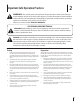
Important Safe Operation Practices 2 WARNING! This symbol points out important safety instructions which, if not followed, could endanger the personal safety and/or property of yourself and others. Read and follow all instructions in this manual before attempting to operate this machine. Failure to comply with these instructions may result in personal injury. When you see this symbol.
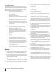
Safe Handling of Gasoline 5. To avoid personal injury or property damage use extreme care in handling gasoline. Gasoline is extremely flammable and the vapors are explosive. Serious personal injury can occur when gasoline is spilled on yourself or your clothes which can ignite. Wash your skin and change clothes immediately. Never run an engine indoors or in a poorly ventilated area. Engine exhaust contains carbon monoxide, an odorless and deadly gas. 6.
Clearing a Clogged Discharge Chute Hand contact with the rotating impeller inside the discharge chute is the most common cause of injury associated with snow throwers. Never use your hand to clean out the discharge chute. To clear the chute: 1. SHUT THE ENGINE OFF! 2. Wait 10 seconds to be sure the impeller blades have stopped rotating. 3. Always use a clean-out tool, not your hands. Maintenance & Storage 1. Never tamper with safety devices. Check their proper operation regularly.
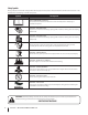
Safety Symbols This page depicts and describes safety symbols that may appear on this product. Read, understand, and follow all instructions on the machine before attempting to assemble and operate. Symbol Description READ THE OPERATOR’S MANUAL(S) Read, understand, and follow all instructions in the manual(s) before attempting to assemble and operate WARNING— ROTATING BLADES Keep hands out of inlet and discharge openings while machine is running.
3 Assembly & Set-Up Contents of Carton • One Snow Thrower • One 20 oz. Bottle 5W-30 Oil • Two Ignition Keys • One Chute Assembly • One Chute Rotation Control (If equip.) • One Set of Drift Cutters (If equip.) • One Snow Thrower Operator’s Manual • One Engine Operator’s Manual NOTE: This Operator’s Manual covers several models. Snow thrower features may vary by model. Not all features in this manual are applicable to all snow thrower models and the snow thrower depicted may differ from yours.
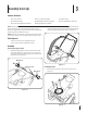
2. Align the holes in the chute base with the holes in the lower chute and secure with the previously removed hex washer screws. See Figure 3-4. Installing the Drift Cutters (If so equipped) 1. Remove the carriage bolts and flange lock nuts from the drift cutters. 2. Install the drift cutters and secure with the carriage bolts and flange lock nuts removed in step 1. See Figure 3-6.
3. Slowly pull the recoil starter handle up towards the eye bolt. 4. Slip the recoil starter rope into the eye bolt from the back of the snow thrower. See Figure 3-7. 5. Securely tighten the eye bolt and handle knob. Set-Up Adding Oil Refer to the Engine Operator’s Manual packed with your snow thrower for information on adding and checking oil. Adding Fuel Refer to the Engine Operator’s Manual packed with your snow thrower for information on adding fuel.
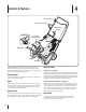
4 Controls & Features Auger Control Recoil Starter Handle Chute Rotation Control EZ Chute Low-Crank Chute Assembly Drift Cutters Auger Shave Plate NOTE: This Operator’s Manual covers several models. Snow thrower features may vary by model. Not all features in this manual are applicable to all snow thrower models and the snow thrower depicted may differ from yours. EZ Chute (If so equipped) See the Engine Operator’s Manual for the location and function of the controls on the engine.
Recoil Starter Handle The recoil starter handle is used to manually start the engine. Chute Rotation Control (If so equipped) The chute rotation control is located on the back of the snow thrower. To rotate the chute to the left, squeeze the lever against the chute rotation control and rotate left. To rotate the chute to the right, squeeze the lever against the chute rotation control and rotate right. Drift Cutters (If so Equipped) The drift cutters are designed for use in deep snow.
5 Operation Starting & Stopping the Engine WARNING! Always keep hands and feet clear of Low-Crank Chute Assembly (If so equipped) 1. moving parts. Do not use a pressurized starting fluid. Vapors are flammable. Rotate the discharge chute to the left or right using the chute rotation control. See Figure 5-2. Chute Control Handle Refer to the Engine Operator’s manual packed with your snow thrower for instructions on starting and stopping the engine.
6 Maintenance & Adjustments Adjustments Auger Control Cable WARNING! Before servicing, repairing or inspecting the snow thrower, disengage the auger control. Stop the engine and remove the key to prevent unintended starting. Shave Plate To check the adjustment of the shave plate, place the machine on a level surface. The wheels, shave plate and auger should all contact the level surface. Note that if the shave plate is adjusted too high, snow may blow under the housing.
Maintenance 3. Lubrication Change the oil and/or the spark plug as instructed in your Engine Operator’s manual. 4. Re-install the lower panel by placing the tabs in the tab slots, lifting the panel into place and secure with the three screws removed in step 2. 5. Tip the snow thrower back to the operating position and pull the starter handle a few times to see if it is difficult to pull. 6.
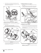
7 Service Replacing Belt To replace the belt follow these instructions and refer to Figure 7-3: 1. Run the snow thrower until the fuel tank is empty. 2. Pull the recoil starter handle until resistance is felt. Then tip the snow thrower back until it rests on the handles. 3. Slide a board up through the auger and through the chute to secure the auger in place. 4. Remove the belt cover by removing the two hex washer screws and one hex lock screw that secure it to the frame. See Figure 7-1.
Replacing Auger Paddles Replacing Shave Plate The snow thrower auger’s rubber paddles are subject to wear and should be replaced if any signs of excessive wear are present. 1. The shave plate is attached to the bottom of the auger housing and is subject to wear. It should be checked periodically. There are two wearing edges and the shave plate can be reversed. 2. Run the snow thrower until the fuel tank is empty. 3. Pull the recoil starter handle until resistance is felt.
8 Troubleshooting Problem Cause Remedy Excessive vibration 1. Loose parts or damaged auger. 1. Stop engine immediately and disconnect spark plug wire. Check for possible damage. Tighten all bolts and nuts. Repair as needed. If the problem persists, take snow thrower to an authorized service dealer. Snow thrower fails to selfpropel 1. Auger control cable out of adjustment. 1. Adjust auger control cable as shown in Maintenance & Adjustments section. 2. Auger drive belt loose or damaged. 2.
9 Replacement Parts Component Part Number and Description 731-08171 Shave Plate 954-04050 Belt V-Type 753-06469 Rubber Auger Paddle Kit (Includes 2 paddles and 12 hex washer screws) 731-05632 Key 946-04782 946-04701 Clutch Cable (Squall 210) Clutch Cable (Squall 2100) 634-04607 634-05036 Wheel Assembly, 7 x 2 (Squall 210) Wheel Assembly, 8 x 2 (Squall 2100) 951-10292 Spark Plug Phone (800) 800-7310 to order replacement parts or a complete Parts Manual (have your full model number and serial
Notes 10 19
Section 10— Notes
Section 10 — Notes 21
FEDERAL and/or CALIFORNIA EMISSION CONTROL WARRANTY STATEMENT YOUR WARRANTY RIGHTS AND OBLIGATIONS MTD Consumer Group Inc, the United States Environmental Protection Agency (EPA), and for those products certified for sale in the state of California, the California Air Resources Board (CARB) are pleased to explain the emission (evaporative and/or exhaust) control system (ECS) warranty on your 2013 and later small off-road spark-ignited engine and equipment (outdoor equipment engine).
10. Add-on or modified parts that are not exempted by the Air Resources Board may not be used. The use of any non-exempted add-on or modified parts by the ultimate purchaser will be grounds for disallowing a warranty claims. MTD Consumer Group Inc will not be liable to warrant failures of warranted parts caused by the use of a non-exempted add-on or modified part.
MANUFACTURER’S LIMITED WARRANTY FOR The limited warranty set forth below is given by Troy-Bilt LLC with respect to new merchandise purchased and used in the United States and/or its territories and possessions, and by MTD Products Limited with respect to new merchandise purchased and used in Canada and/or its territories and possessions (either entity respectively, “Troy-Bilt”). b.
Medidas importantes de seguridad • Configuración • Funcionamiento • Mantenimiento • Servicio • Solución de problemas • Garantía Manual del Operador — Squall 2100 Que Aparecen — Máquina quitanieve de etapa única Squall 210 & Squall 2100 ADVERTENCIA LEA Y RESPETE TODAS LAS NORMAS DE SEGURIDAD E INSTRUCCIONES INCLUIDAS EN ESTE MANUAL ANTES DE PONER EN FUNCIONAMIENTO ESTA MÁQUINA. SI NO RESPETA ESTAS INSTRUCCIONES PUEDE PROVOCAR LESIONES PERSONALES.
1 Al propietario Gracias Gracias por comprar una MTD máquina quitanieve. La misma ha sido diseñada cuidadosamente para brindar excelente rendimiento si se la opera y mantiene correctamente. Por favor lea todo este manual antes de operar el equipo. Le indica cómo configurar, operar y mantener la máquina con seguridad y fácilmente. Por favor asegúrese de seguir cuidadosamente y en todo momento las prácticas de seguridad recomendadas, y hacérselas seguir a cualquier otra persona que opere la máquina.
2 Medidas importantes de seguridad ¡ADVERTENCIA! La presencia de este símbolo indica que se trata de instrucciones importantes de seguridad que se deben respetar para evitar poner en peligro su seguridad personal y/o material y la de otras personas. Lea y siga todas las instrucciones de este manual antes de poner en funcionamiento esta máquina. Si no respeta estas instrucciones puede provocar lesiones personales. Cuando vea este símbolo.
Manejo seguro de la gasolina Para evitar lesiones personales o daños materiales tenga mucho cuidado cuando trabaje con gasolina. La gasolina es sumamente inflamable y sus vapores pueden causar explosiones. Si se derrama gasolina encima o sobre la ropa se puede lesionar gravemente ya que se puede incendiar. Lávese la piel y cámbiese de ropa de inmediato. a. b. Utilice sólo los recipientes para gasolina autorizados. Apague todos los cigarrillos, cigarros, pipas y otras fuentes de combustión. c.
21. Si se presentan situaciones que no están previstas en este manual, sea cuidadoso y use el sentido común. Póngase en contacto con Asistencia al Cliente para solicitar ayuda y el nombre del distribuidor de servicio más cercano. 10. Nunca almacene la máquina o el recipiente de combustible en un espacio cerrado donde haya fuego, chispas o luz piloto como por ejemplo, calentadores de agua, hornos, secadores de ropa, etc. Borrado de una Tolva de descarga obstruida 11.
Símbolos de Seguridad Esta página describe los símbolos y figuras de seguridad internacionales que pueden aparecer en este producto. Lea el manual del operador para obtener la información terminada sobre seguridad, reunirse, operación y mantenimiento y reparación. Símbolo Descripción LEA EL MANUAL DEL OPERADOR (S) Lea, entienda, y siga todas las instrucciones en el manual (es) antes de intentar reunirse y funcionar.
3 Montaje y Configuración Contenido de la caja de cartón • Una máquina quitanieve • Una botella de 20 oz. de aceite 5W-30 • Dos llaves de encendido • Un conjunto de canal • Un control de rotación del canal (si viene equipado). • Un conjunto de cortadores de desplazamiento de nieve (si viene equipado). • Un Manual del Operador de la Máquina Quitanieve • Un Manual de operación del motor NOTA: Este manual de operación cubre distintos modelos.
Instalación del canal 1. Extraiga los tornillos para arandela hexagonal de la base del canal. Vea la Figura 3-3. Instalación del control de rotación del canal (si viene equipado) Para instalar el control de rotación del canal (solamente los modelos así equipados) proceda de la siguiente manera: 1. Retire la tuerca de seguridad hexagonal y el tornillo de la máquina del control de rotación del canal. Vea la Figura 3-5.
Instalación de los cortadores de desplazamiento de nieve (si vienen equipados) 1. Extraiga los pernos del carro y las tuercas de seguridad con brida de los cortadores de desplazamiento de nieve. 2. Instale los cortadores y asegure con los pernos del carro y las tuercas de seguridad con brida extraídas en el paso 1. Vea la Figura 3-6. 4. Deslice el cable de arranque de arranque en la argolla de la parte posterior de la máquina quitanieves. Véase la Figura 3-7.
4 Controles y Características Control de la barrena Manija del arrancador de retroceso Control de rotación del canal Canal EZ Montaje de la manivela del canal inferior Cortadores de desplazamiento de nieve Barrena Placa de raspado NOTA: Este manual de operación cubre distintos modelos. Las características técnicas de la máquina quitanieve pueden variar según los modelos.
Manija del arrancador de retroceso La manija del arrancador de retroceso se utiliza para encender manualmente el motor. Control de rotación del canal (si viene equipado) El control de rotación del canal está ubicado en la parte posterior de la máquina quitanieve. Para rotar el canal hacia la izquierda, apriete la palanca contra el control de rotación del canal y rote hacia la izquierda. Para rotar el canal hacia la derecha, apriete la palanca contra el control de rotación del canal y rote hacia la derecha.
5 Funcionamiento Arranque y detención del motor ¡ADVERTENCIA! Siempre mantenga las manos y Conjunto de la manivela del canal inferior (de venir equipado) 1. los pies alejados de las partes móviles. No utilice fluidos comprimidos para arrancar. Los vapores son inflamables. Consulte el manual de operación del motor embalado con su máquina quitanieve para ver las instrucciones sobre cómo arrancar y detener el motor.
6 Mantenimiento y Ajustes Ajustes 6. ¡ADVERTENCIA! Antes de realizar tareas de mantenimiento, reparación o inspección en la máquina quitanieve, desengrane el control de la barrena. Apague el motor y retire la llave para evitar el encendido accidental del motor. Placa de raspado Para verificar el ajuste de la placa de raspado, ubique la unidad sobre una superficie nivelada. Las ruedas, la placa de raspado y las barrenas deben tocar la superficie nivelada.
Mantenimiento 3. Lubricación Cambie el aceite y/o bujía como se instruye en su manual de operación del motor. 4. Instale nuevamente el panel inferior colocando las lengüetas en sus ranuras, levantando el panel para colocarlo en su lugar y sujételo con los tres tornillos que extrajo en el paso 2. 5. Incline la máquina quitanieve nuevamente a la posición de funcionamiento y jale de la manija de arranque varias veces para ver si es difícil jalar de la misma. 6.
7 Servicio Reemplazo de las correas 1. 2. 3. 4. 6. Ponga en marcha la máquina quitanieve hasta que el tanque de combustible esté vacío. Jale de la manija del arrancador de retroceso hasta sentir resistencia. Luego incline la máquina quitanieve hacia atrás hasta que quede apoyada sobre las manijas. Deslice una tabla hacia arriba a través de la barrena y a través del canal para sujetar la barrena en su lugar.
Reemplazo de las paletas de la barrena Reemplazo de la placa de raspado Las paletas de caucho de la barrena de la máquina quitanieve se desgastan y se las debe cambiar si se presentan signos de desgaste excesivo. 1. La placa de raspado está adosada al fondo de la caja de la barrena y sujeta a desgaste. Se la debe controlar periódicamente. La placa de raspado tiene dos bordes de desgaste y se la puede invertir. 2. Ponga en marcha la máquina quitanieve hasta que el tanque de combustible esté vacío. 3.
8 Solución de Problemas Problema Causa Solución Vibración excesiva 1. Hay piezas que están flojas o la barrena está dañada. 1. Detenga el motor de inmediato y desconecte el cable de la bujía. Controle si la máquina está dañada. Ajuste todos los pernos y las tuercas. Realice las reparaciones necesarias. Si el problema continúa, lleve la unidad a un distribuidor de servicio autorizado. La máquina quitanieve no se autopropulsa 1. El cable del control de la barrena necesita un ajuste. 1.
DECLARACIÓN FEDERAL y/o DE CALIFORNIA SOBRE GARANTÍAS EN EL CONTROL DE EMISIONES SUS DERECHOS Y OBLIGACIONES EN CUANTO A LA GARANTÍA MTD Consumer Group Inc, la Agencia de Protección Medioambiental de los Estados Unidos (EPA), y para aquellos productos certificados para su venta en el estado de California, el Departamento de los Recursos del Aire de California (CARB) se complacen en explicar la garantía que cubre al sistema de control (ECS) de emisiones (evaporativas y/o de escape) de su equipo y motor (moto
6. El propietario del motor de equipos de exteriores no deberá pagar el trabajo de diagnóstico directamente asociado con una pieza garantizada defectuosa en relación con las emisiones, siempre y cuando dicho trabajo de diagnóstico se realice en un centro cubierto por la garantía. 7. MTD Consumer Group Inc es responsable por daños causados a otros componentes de motores o equipos derivados de la falla bajo garantía de cualquier pieza garantizada. 8.
GARANTÍA LIMITADA DEL FABRICANTE PARA La siguiente garantía limitada es otorgada por Troy-Bilt LLC con respecto a nuevos productos adquiridos y utilizados en Estados Unidos y/o sus territorios y posesiones, y por MTD Products Limited con respecto a nuevos productos adquiridos y utilizados en Canadá y/o sus territorios y posesiones (cualquiera de las dos entidades, respectivamente, “Troy-Bilt”). Esta garantía es adicional a la garantía de emisiones aplicables proporcionada con el producto.