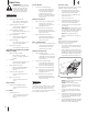
Safe Operation Practices • Set-Up • Operation • Service • Troubleshooting Operator’s Manual Snow Thrower Single-Stage (200 Series) Table of Contents Safe Operation Practices......................................... 2 Assembly & Set-Up................................................... 5 Controls & Operation............................................... 8 Product Care............................................................10 Español....................................................................
1 Important Safe Operation Practices WARNING! This symbol points out important safety instructions which, if not followed, could endanger the personal safety and/or property of yourself and others. Read and follow all instructions in this manual before attempting to operate this machine. Failure to comply with these instructions may result in personal injury. When you see this symbol.
5. Do not overload machine capacity by attempting to clear snow at too fast of a rate. Snow thrower shave plates and skid shoes are subject to wear and damage. For your safety protection, frequently check all components and replace with original equipment manufacturer’s (OEM) parts only. “Use of parts which do not meet the original equipment specifications may lead to improper performance and compromise safety!” 6. Never operate this machine without good visibility or light.
Safety Symbols This page depicts and describes safety symbols that may appear on this product. Read, understand, and follow all instructions on the machine before attempting to assemble and operate. Symbol Description READ THE OPERATOR’S MANUAL(S) Read, understand, and follow all instructions in the manual(s) before attempting to assemble and operate. WARNING — ROTATING BLADES Keep hands out of inlet and discharge openings while machine is running. There are rotating blades inside.
2 Assembly & Set-Up Thank You Thank you for purchasing this product. It was carefully engineered to provide excellent performance when properly operated and maintained. Please read this entire manual prior to operating the equipment. It instructs you how to safely and easily set up, operate and maintain your machine. Please be sure that you, and any other persons who will operate the machine, carefully follow the recommended safety practices at all times.
Tools Required 4. • Adjustable Wrench or Socket Set • Phillips Head Screwdriver On models with adjustable handles, place the handle in the desired position and then install wing knobs (a) and carriage bolts (b) in the appropriate hole and secure the handle. See Figure 2-5. 3. Align the holes in the chute base with the three tabs (b) in the lower chute as shown in Figure 2-8, Inset I. Secure the chute base with the hex washer screws (a) removed in Step 2. See Figure 2-8. Handle Assembly 1.
Installing the Chute Rotation Control (If Equipped) 2. Using the hex washer screws (a), install the chute rotation control assembly. See Figure 2-12. Installing the Recoil Starter Handle onto the Upper Handle NOTE: Refer to Figure 2-1 and continue to your 1. Remove the eye bolt and handle knob from the manual bag. Lower 2-Way Chute 2. Place the eye bolt (a) and handle knob (b) on the upper handle as shown in Inset I in Figure 2-15. Do not fully tighten the hardware until instructed to do so.
3 Controls & Operation Headlight † Auger Control Lever Upper 2-Way Chute † Chute Tilt Control † Chute Tilt Control Recoil Starter Handle Chute Rotation Control Chute Rotation Control † Chute Assembly (See Insets for Specific Chute Types) Lower 2-Way Chute † Chute Rotation Control E-Z Chute™ † Drift Cutter † Auger Shave Plate Chute Assembly Chute Handle † † — If Equipped Figure 3-1 Snow thrower controls and features are described below and illustrated in Figure 3-1.
Choke Lever Engaging the Drive Upper 2-Way Chute (If Equipped) Activating the choke control closes the choke plate on carburetor and aids in starting engine. The choke lever slides between the RUN and CHOKE positions. Lift up slightly on the handle to allow the rubber paddles on the auger to contact the pavement and propel the snow thrower forward. Pushing downward on the handle will raise the auger off the ground and stop the forward motion.
4 Product Care WARNING! Before servicing, repairing or inspecting the snow thrower, disengage the auger control lever. Stop the engine and remove the safety key to prevent unintended starting. Excessive Vibration Off-Season Storage 1. If the unit will not be used for 30 days or longer, follow the storage instructions below. Loose parts or damaged auger. • Troubleshooting Engine Fails to Start 1. Choke not in CHOKE position • 2. Clean, adjust gap or replace. See Engine Operator’s Manual. • 3.
6. If the recoil starter handle is difficult to pull, remove the spark plug as instructed in your Engine Operator’s Manual and pull the handle several times to ensure that any oil trapped in the head is removed. 4. Tip the snow thrower back to the operating position and pull the recoil starter handle a few times to see if it is difficult to pull. 5.
10. Squeeze the auger control lever against the upper handle and reinstall the belt cover removed in Step 4. 11. Remove the board from the auger and chute. 12. Tip the snow thrower back to the operating position and pull the recoil starter handle a few times to see if it is difficult to pull. 13.
Medidas de seguridad • Configuración • Funcionamiento • Servicio • Solución de problemas Manual del Operador Máquina quitanieves De etapa única (Serie 200) Índice Medidas de seguridad............................................. 2 Solución de problemas...........................................12 Montaje y configuración......................................... 5 Piezas/Garantía...... Consulte el suplemento que se Controles y funcionamiento....................................
1 Importantes medidas de seguridad ¡ADVERTENCIA! La presencia de este símbolo indica que se trata de instrucciones de seguridad importantes que se deben respetar para evitar poner en peligro su seguridad personal y/o material y la de otras personas. Lea y cumpla todas las instrucciones de este manual antes de intentar operar esta máquina. Si no respeta estas instrucciones puede provocar lesiones personales.
14. Corte la corriente a la barrena cuando transporte la máquina o cuando la misma no está en uso. 15. Nunca opere la máquina a altas velocidades de desplazamiento sobre superficies resbaladizas. Mire hacia abajo y hacia atrás y tenga cuidado cuando vaya marcha atrás. 16. Si la máquina comenzara a vibrar de manera anormal, detenga el motor, desconecte el cable de la bujía y póngala de manera que haga masa contra el motor. Revise cuidadosamente para detectar daños.
Símbolos de seguridad En esta página se presentan y describen los símbolos de seguridad que pueden aparecer en este producto. Lea, entienda y siga todas las instrucciones incluidas en la máquina antes de intentar armarla y hacerla funcionar. Símbolo Descripción LEA LOS MANUALES DEL OPERADOR Lea, entienda y siga todas las instrucciones incluidas en los manuales antes de intentar armarla y hacerla funcionar.
2 Montaje y configuración Gracias Gracias por comprar este producto. Se ha diseñado cuidadosamente para brindar excelente rendimiento si se opera y mantiene correctamente. Por favor lea todo este manual antes de hacer funcionar el equipo. El manual le indica cómo configurar, operar y mantener la máquina de manera fácil y segura. Por favor asegúrese de que usted, y cualquier otra persona que utilice la máquina, siga atentamente y en todo momento las medidas de seguridad recomendadas.
Herramientas necesarias 4. • Llave ajustable o juego de llaves de vaso • Destornillador de cabeza Phillips En los modelos con manija ajustable, ubique la manija en la posición deseada y luego instale las perillas de aletas (a) y los pernos de carro (b) en el orificio adecuado y sujete la manija. Consulte la Figura 2-5. 3. Alinee los orificios de la base del canal con las tres lengüetas (b) del canal inferior como se indica en la Figura 2-8, Recuadro I.
Instalación del control de rotación del canal (si viene equipado) 2. Usando los tornillos de cabeza hexagonal (a), instale el conjunto del control de rotación del canal. Consulte la Figura 2-12. NOTA: Consulte la Figura 2-1 y continúe hasta el estilo de canal que corresponde al suyo. Canal inferior de 2 direcciones 1. Retire la tuerca de seguridad hexagonal (a) y el tornillo de la máquina (b) del conjunto del control de rotación del canal. Consulte el Recuadro I de la Figura 2-10.
3 Controles y funcionamiento Faro delantero † Palanca de control de la barrena Canal superior de 2 direcciones † Control de inclinación del canal † Control de inclinación del canal Manija del arrancador de retroceso Control de rotación del canal Control de rotación del canal † Conjunto del canal (Vea insertos para los tipos específicos de canales) Canal inferior de 2 direcciones † Control de rotación del canal Canal E-Z Chute™ † Cortador de desplazamiento de nieve † Auger Conjunto del canal Manij
Palanca del cebador Activación de la transmisión Al activar el control del cebador se cierra la placa de cebado del carburador y se ayuda a arrancar el motor. La palanca del cebador se desliza entre las posiciones RUN (funcionamiento) y CHOKE (cebador). Levante apenas la manija para permitir que las paletas de caucho de la barrena toquen el pavimento e impulse la máquina quitanieves hacia adelante. Si presiona la manija hacia abajo, elevará la barrena del suelo y detendrá el avance de la máquina.
4 Servicio ¡ADVERTENCIA! Antes de realizar tareas de mantenimiento, reparación o inspección en la máquina quitanieves, desengrane la palanca de control de la barrena. Pare el motor y retire la llave de seguridad para evitar el encendido accidental del motor. Solución de problemas 2. Lubrique la máquina como se indica en la sección Lubricación. Ajustes 3. Almacénela en un lugar limpio y seco. Placa de raspado 4.
4. 5. Incline la máquina quitanieves nuevamente a la posición de funcionamiento y tire del arrancador de retroceso algunas veces para comprobar si resulta difícil tirar de él. 4. Para sacar la cubierta de la correa saque los dos tornillos de cabeza hexagonal (a) y un tornillo de seguridad hexagonal (b) que la sujetan al bastidor. Consulte la Figura 4-4.
5 Solución de problemas Problema Causa El motor no arranca El motor funciona de manera errática/RPM desiguales (oscilación o sobretensión) 1. El cebador no está en la posición CHOKE (cebador). 1. Ponga el cebador en la posición CHOKE (cebador). Consulte el Manual del operador del motor. 2. Se ha desconectado el cable de bujía. 2. Conecte el cable a la bujía. Consulte el Manual del operador del motor. 3. El tanque de combustible está vacío o el combustible se ha echado a perder. 3.