
Operating Guide


14 SECTION 2 — ASSEMBLY & SET-UP
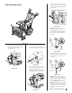
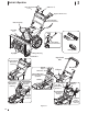
5. Insert other end of chute control rod into
coupler below handle panel. Make sure
to line up flat end of rod and flat end
of coupler. You may need to rotate rod
around until these two surfaces line up.
See Figure 2-42 inset.
Figure 2-44
6. Push chute control rod toward the
control panel until hole in rod lines up
with middle hole in chute control input
and insert cotter pin (a) removed in
Step 1. See Figure 2-43.
(a)
Figure 2-45
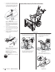
NOTE:
There is a reference hole
provided at rear end of control rod to
help know when holes are vertical.
NOTE: Hole furthest from chute
control head is used to achieve
further engagement of chute control
rod into coupler if required. Refer to
Service section for Chute Control Rod
adjustment on page 22.
Hole closest to chute control head is
used for manual movement of chute
assembly if required. Refer to Controls &
Operation section on page 18.
7. Check that cables are properly routed
through cable guide on top of engine.
See Figure 2-30.
NOTE: For smoothest operation, cables
should all be to left of chute directional
control rod.
STOP
STOP! Continue to Set-Up on
page 14.
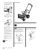
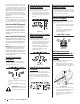
E-Z Chute Control™
Figure 2-46
The E-Z Chute™ does not require any installation.
STOP
STOP! Continue to Set-Up.
Set-Up
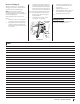
Shear Pins Storage (If Equipped)
On select units, holes are provided in the rear
of the handle panel for shear pin (a) and
bow-tie cotter pin (b) storage as shown in
Figure 2-47. If not provided, make sure to store
them in a safe place until needed.
(a)
(b)
Figure 2-47
NOTE:
Three stage units come with four (4)
shear pins and bow-tie cotter pins.
Chute Clean-Out Tool
The chute clean-out tool is fastened to the top
of the auger housing with a mounting clip. See
Figure 2-48.
Figure 2-48