
Operating Guide


16 SECTION 2 — ASSEMBLY & SET-UP
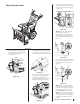
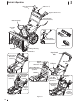
4. Adjust the shave plate on units with
adjustable shave plates so that it is
roughly ⁄” above the skid shoes. On
other units the skid shoes can be
adjusted to ⁄” below the shave plate.
Reinstall and tighten the carriage bolts
(b) and hex nuts (c) all bolts securely. See
Figure 2-52 and Figure 2-53.
Auger Control
WARNING! Prior to operating
your unit, carefully read and
follow all instructions below.
Perform all adjustments to verify
your equipment is operating
safely and properly.
Refer to Controls & Operation section (page 17)
for the location of auger control lever and
check adjustment as follows:
1. When auger control lever is released and
in disengaged “UP” position, the cable
should have very little slack. It should
NOT be tight.
2. In a well-ventilated area, start the snow
thrower engine. Refer to your Engine
Operator’s Manual.
3. While standing in the operator’s position
(behind the unit), depress the auger
control lever to engage auger.
4. Allow auger to remain engaged for
approximately ten (10) seconds before
releasing auger control lever. Repeat this
several times.
5. With auger control lever in disengaged
“UP” position, walk to front of machine.
6. Confirm that auger has completely
stopped rotating and shows NO signs
of motion. If auger shows ANY signs
of rotating, immediately return to
operator’s position and shut OFF engine.
Wait for ALL moving parts to stop before
readjusting auger control lever.
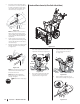
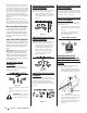
7. To readjust the auger control cable,
loosen upper hex screw (a) on all on
unit sexcept the E-Z Chute™ unit. auger
control bracket. See Figure 2-54.
Auger Control
Bracket
(a)
Figure 2-54
8. On E-Z Chute™ models, loosen the rear
hex screw on the auger control bracket.
See Figure 2-55.
Figure 2-55
9. Position bracket upward on all
units except the E-Z Chute™, push
the adjustment bracket forward on
those units to provide more slack (or
downward/rearward to increase cable
tension). See Figure 2-54 or Figure 2-55
depending on your unit.
10. Retighten upper/rear hex screw (a).
11. Repeat the steps to verify proper
adjustment has been achieved.
Shift Cable (If Equipped)
If full range of speeds (forward and reverse)
cannot be achieved, adjust shift cable as
follows:
1. Place shift lever in fastest forward speed
position.
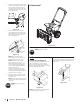
2. Loosen hex nut (a) on shift cable index
bracket. See Figure 4-9.
(a)
Figure 2-56
3. Pivot bracket downward to take up slack
in cable.
4. Retighten hex nut.
Shift Rod (If Equipped)
If full range of speeds (forward and reverse)
cannot be achieved, adjust shift rod as follows:
1. Place shift lever in fastest forward speed
position.
2. Remove cotter pin (a) and washer (b)
from adjustment ferrule on shift rod and
pull it out from shift lever. See Figure
2-57.
(a)
(b)
Figure 2-57
12. Pivot shift bracket downward as far as it
will go. See Figure 2-58.
Figure 2-58
13. Rotate ferrule up or down on shift rod
as necessary until it lines up with upper
hole in shift lever. Refer to Figure 2-57
inset.
14. Insert the ferrule into the upper hole and
secure with the washer and cotter pin.