
Operating Guide


20 SECTION 3 — CONTROLS & OPERATION
*On select models, the drive control lever also
locks the auger control lever so that you can
operate the chute directional control without
interrupting the snow throwing process. If the
auger control lever is engaged simultaneously
with the drive control lever, the operator can
release the auger control lever (on the left
handle) and the augers will remain engaged.
Release both control levers to stop augers and
wheel drive.
NOTE: Always release drive control lever
before changing speeds on all units except the
800-series hydro. Failure to do so will result in
increased wear on your machine’s drive system.
Drive Control Bail (If Equipped)
Located on the underside of the upper
handle, the drive control bail is used
to engage/disengage wheels. Squeeze
the drive control bail against the upper
handle to engage the wheels; release to
disengage.
Auger Control Bail (If Equipped)
The auger control bail is adjacent to the
upper handle. Squeeze the auger control
bail against the upper handle to engage
the augers; release to disengage the
augers.
IMPORTANT: Refer to the Auger Control
information in the Assembly & Set-Up
section prior to operating your snow
thrower. Read and follow all instructions
carefully and perform all adjustments
to verify your snow thrower is operating
safely and properly.
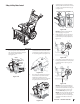
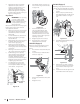
Steering Trigger Controls
(If Equipped)
The left and right wheel steering trigger
controls are located on the underside of the
handles. Refer to Figure 3-6.
Figure 3-6
• Squeeze the right trigger control to turn
right.
• Squeeze the left trigger control to turn
left.
CAUTION: Operate the snow
thrower in open areas until you
are familiar with these controls.
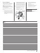
2-Way Chute Directional Control
Joystick (If Equipped)
The 2-Way chute directional control joystick is
located on the left side of the dash panel.
• To change direction in which snow is
thrown, squeeze button on joystick and
pivot joystick to right or to the left. See
Figure 3-7.
Figure 3-7
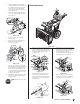
4-Way Chute Directional Control
Joystick (If Equipped)
The 4-Way chute directional control joystick is
located on the left side of the dash panel.
• To change the direction in which snow
is thrown, squeeze the button on the
joystick and pivot the joystick to the
right or to the left. See Figure 3-8.
• To change the angle/distance which
snow is thrown, pivot the joystick
forward or backward.
Figure 3-8
Overhead Chute Directional Control
(If Equipped)
The overhead chute directional control is
located at the rear of the snowthrower towards
the left side of the unit under the handle
panel. To change the direction in which snow
is thrown, rotate chute directional control. See
Figure 3-9.
Figure 3-9
Standard/U-Joint Chute Directional
Control (If Equipped)
The standard/U-Joint chute directional control
is located on the left side of the unit. To change
direction in which snow is thrown, rotate chute
directional control. See Figure 3-9.
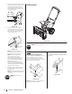
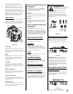
Electric Chute Directional Control
Joystick (If Equipped)
The electric chute directional control joystick
is located on the right side of the dash panel.
Refer to Figure 3-10.
• To change the direction in which snow is
thrown, move the joystick to the right or
to the left.
• To change the angle/distance which
snow is thrown, pivot the joystick
forward or backward.
DIRECTIONAL CONTROL
ELECTRIC CHUTE
CHUTE
ROTATE
LEFT
CHUTE
ROTATE
RIGHT
CHUTE TILT UP
CHUTE TILT DOWN
Figure 3-10
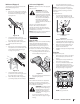
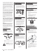
Manual Chute Directional
Control (Equipped on units with
Electric Chute Directional Control
Joystick)
Proceed as follows to utilize manual chute
directional control if needed:
1. Remove cotter pin (a) from either of the
holes furthest from the chute assembly on
chute rotation assembly. See Figure 3-11.
(a)
Figure 3-11
2. Push in chute control rod until the hole
in it lines up with the third hole in chute
rotation assembly. See Figure 3-11.
3. Reinsert cotter pin (a) through this hole
and chute control rod as shown in
Figure 3-11.