Safe Operation Practices • Set-Up • Operation • Service • Troubleshooting OPERATOR’S MANUAL Snow Thrower 2-Stage and 3-Stage (300, 500, 600 & 800 Series) Table of Contents Safe Operation Practices ........................................ 2 Product Care .......................................................... 22 Assembly & Set-Up .................................................. 5 Parts/Warranty.............. See Separate Supplement Controls & Operation .............................................
1 Important Safe Operation Practices WARNING! This symbol points out important safety instructions which, if not followed, could endanger the personal safety and/or property of yourself and others. Read and follow all instructions in this manual before attempting to operate this machine. Failure to comply with these instructions may result in personal injury. When you see this symbol. HEED ITS WARNING! CALIFORNIA PROPOSITION Preparation Thoroughly inspect the area where the equipment is to be used.
14. 15. 16. 17. 18. Release auger control lever to disengage power to the auger when transporting or not clearing snow. 1. Never operate machine at high transport speeds on slippery surfaces. Look down and behind and use care when backing up. Never tamper with safety devices. Check their proper operation regularly. Refer to the maintenance and adjustment sections of this manual. 2.
Safety Symbols This page depicts and describes safety symbols that may appear on this product. Read, understand, and follow all instructions on the machine before attempting to assemble and operate. Symbol Description READ THE OPERATOR’S MANUAL(S) Read, understand, and follow all instructions in the manual(s) before attempting to assemble and operate. WARNING— ROTATING BLADES Keep hands out of inlet and discharge openings while machine is running. There are rotating blades inside.
2 Assembly & Set-Up Thank You Thank you for purchasing this product. It was carefully engineered to provide excellent performance when properly operated and maintained. reserve the right to change product specifications, designs and equipment without notice and without incurring obligation. Please read this entire manual prior to operating the equipment. It instructs you how to safely and easily set up, operate and maintain your machine.
Tools Required 5. • Adjustable Wrench or Socket Set • Needle Nose Pliers Pivot handle upward and align the lower handle. See Figure 2-4. Remove and discard any rubber bands, if present. They are for packaging purposes only. 2. Remove the wing knob (a), saddle washer (b), handle tab (c) and carriage screw (d) on each side of the lower handle. See Figure 2-6. Handle Assembly (d) Refer to Figure 2-1 and proceed to your applicable chute style.
5. Insert a carriage screw (a) from the outside through a handle tab (b), the upper (c) and lower handles (d), a saddle washer (e) and into the wing knob (f). Repeat on the other side. Tighten the wing knobs (f) on each side of the handle. Refer to Figure 2-8. (d) (c) (b) (d) (a) (a) (c) (c) (c) (d) (b) Figure 2-9 (e) 6.
Chute Assembly Options Refer to Figure 2-1 and proceed to your applicable Chute Control Style on pages 8-14. Standard Side Crank Chute Control Figure 2-10 1. Position chute assembly over base. See Figure 2-11. 2. Close flange keepers to secure chute assembly to chute base. Flange keepers will click into place when properly secure. See Figure 2-12. Chute Directional Control Assembly 1. Remove plastic cap (if present), flat washer (a) and hairpin clip (b) from end of chute directional control assembly.
U-Joint Side Crank Chute Control Figure 2-14 1. Position chute assembly over base. See Figure 2-15. 2. Close flange keepers to secure chute assembly to chute base. Flange keepers will click into place when properly secure. See Figure 2-16. 2. Insert unattached chute directional control assembly into eye bolt on left side of handle assembly. See Figure 2-17. (a) Figure 2-15 Figure 2-17 Figure 2-16 NOTE: Ensure the lower chute is secured to the flange on the chute base.
3. Overhead Chute Control (w/ Chute Control Rod) Finish securing chute control head to chute support bracket with wing nut (a) and hex screw (b) removed in Step 1. See Figure 2-21. (b) (a) Figure 2-21 4. Insert chute control rod into the support bracket on rear of the dash panel. See Figure 2-22. Figure 2-18 1. Remove wing nut (a) and hex screw (b) from chute control head and clevis pin (c) and cotter pin (d) from chute support bracket. Position chute assembly (forward-facing) over chute base.
4. 2-Way & 4-Way Chute Control Squeeze trigger on joystick and rotate chute by hand to face forward. The holes in chute control input will be facing up. See Figure 2-28. Chute Control Input Top View Joystick Figure 2-28 NOTE: Chute will not rotate without squeezing trigger on joystick. 5. Rotate joystick to one o’clock position so that indicator arrow on pinion gear below control panel faces upward. See Figure 2-29. Figure 2-24 1.
7. Push chute control rod toward control panel until hole in rod lines up with hole in chute control input closest to chute control head and insert hairpin clip (a) removed in Step 1. See Figure 2-31. Overhead Chute Control (w/ Flex Shaft & Steel Chute) (a) Figure 2-31 NOTE: Second hole is used to achieve further engagement of chute control rod into pinion gear if required. Refer to Service section for Chute Control Rod adjustments. 8.
5. Insert flex shaft (b) removed during Handle Assembly from lower handle into rear of chute directional control head. See Figure 2-36. Secure flex shaft to chute control head with hairpin clip (a) removed in Step 4. 6. Insert hex end of flex shaft into chute control rod coupling under dash panel. See Figure 2-37. Electric Chute Control Figure 2-37 7. Ensure speed selector is in fastest forward speed. 8. Remove cotter pin (a) and washer (b) from ferrule on end of shift rod. See Figure 2-38 inset.
5. Insert other end of chute control rod into coupler below handle panel. Make sure to line up flat end of rod and flat end of coupler. You may need to rotate rod around until these two surfaces line up. See Figure 2-42 inset. 6. Push chute control rod toward the control panel until hole in rod lines up with middle hole in chute control input and insert cotter pin (a) removed in Step 1. See Figure 2-43. E-Z Chute Control™ Figure 2-44 (a) Figure 2-46 The E-Z Chute™ does not require any installation.
Drift Cutters (If Equipped) Tire Pressure (If Applicable) The drift cutters are mounted inverted at the factory for shipping purposes. NOTE: Not applicable to those units equipped with airless tires. Standard WARNING! Under any 1. circumstance do not exceed manufacturer’s recommended psi. Equal tire pressure should be maintained at all times. Excessive pressure when seating beads may cause tire/rim assembly to burst with force sufficient to cause serious injury.
4. Adjust the shave plate on units with adjustable shave plates so that it is roughly 1⁄8” above the skid shoes. On other units the skid shoes can be adjusted to 1⁄8” below the shave plate. Reinstall and tighten the carriage bolts (b) and hex nuts (c) all bolts securely. See Figure 2-52 and Figure 2-53. 8. On E-Z Chute™ models, loosen the rear hex screw on the auger control bracket. See Figure 2-55.
Drive Control (If Equipped) 3. When drive control lever is released and in disengaged “UP” position, cable should have very little slack. It should NOT be tight. NOTE: If excessive slack is present in drive cable or if unit’s drive is disengaging intermittently during operation, the cable may be in need of adjustment. Check adjustment of drive control leveras follows: 1. With drive control lever released, push unit gently forward. It should roll freely. 2.
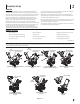
3 Controls & Operation Shift Lever Drive Control Lever † † Auger Control Lever † Standard Chute Directional Control † Chute Assembly Clean Out Tool Drift Cutters † U-Joint Chute Directional Control † LED Light Bar † Auger Housing Augers Skid Shoe Auger Control Bail † Overhead Chute Directional Control † Heated Grips † Shift Lever E-Z Chute † Drive Control Bail † 4-Way/2-Way Chute Directional Control Joystiick † Shift Rod Manual Chute Directional Control † Electric Chute Directional Control
Snow thrower controls and features are described below and illustrated in Figure 3-1. NOTE: This Operator’s Manual covers several models. Snow thrower features may vary by model. Not all features in this manual are applicable to all snow thrower models and the snow thrower depicted may differ from yours. NOTE: All references to the left or right side of the snow thrower are from the operator’s position. Any exceptions will be noted.
*On select models, the drive control lever also locks the auger control lever so that you can operate the chute directional control without interrupting the snow throwing process. If the auger control lever is engaged simultaneously with the drive control lever, the operator can release the auger control lever (on the left handle) and the augers will remain engaged. Release both control levers to stop augers and wheel drive.
4. Grasp indented portion of chute control rod and manually rotate chute assembly to the right or to the left. See Figure 3-12. 1. With the throttle control in the Fast (rabbit) position, move the shift lever into one of the six forward (F) positions or two reverse (R) positions on 6-speed units or in the desired position on the Hydro units. Select a speed appropriate for the snow conditions and a comfortable pace. 2. Squeeze the drive control lever against the handle and the snow thrower will move.
4 Product Care WARNING! Before servicing, repairing or inspecting the snow thrower, disengage the auger control lever. Stop the engine and remove the safety key to prevent unintended starting. Excessive Vibration 1. Loose parts or damaged auger. • Troubleshooting Stop engine immediately and disconnect the spark plug wire. Check for possible damage. Tighten all nuts and bolts. Repair as needed. If the problem persists, contact an authorized service center.
To remove shave plate: Off-Season Storage 1. Allow the engine to run until it is out of fuel. Do not attempt to pour fuel from the engine. If the unit will not be used for 30 days or longer, follow the storage instructions below. 2. Carefully pivot unit up and forward so that it rests on the auger housing. 3. Remove carriage bolts (a) and hex nuts (b) which attach it to auger housing. SeeFigure 4-2. 1. Run engine until fuel tank is empty and it stops due to lack of fuel.
Skid Shoes Refer to Assembly & Set-up section (page 15) for instructions on adjusting skid shoes. Chute Bracket (If Equipped) If spiral at bottom of the chute directional control is not fully engaging with chute assembly, chute bracket needs to be adjusted. To do so: 1. U-Joint (a) (a) the LED headlight on top of the auger housing, make sure to unplug the wire harness before removing the belt cover as shown in Figure 4-11.
7. Loosen and remove shoulder bolt (a) which acts as a belt keeper and unhook the spring (b) from the frame.. See Figure 4-14. 3. Remove the self-tapping screw (a) shown in Figure 4-16, and press the plastic tabs (b) to release the belt cover (c). Pull the belt cover (c) up and out from around the engine and chute assembly. Set it aside and save. 8. After replacing auger belt, perform Auger Control test in Assembly & Set-Up section (page 16).
9. Reassemble the belt cover on the snow thrower 10. Reassemble the belt keeper to the housing. 5. Carefully remove hex nut (a) which secures hex shaft to equipment frame and lightly tap the shaft’s end to dislodge ball bearing from right side of frame. See Figure 4-22.
Notes 5 27
SECTION 5 — NOTES