
Operator's Manual


7
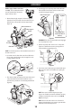
ASSEMBLY
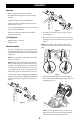
6. Attach the two carriage bolts (b) and nuts (a) removed in Step
2. Finish securing the handle by tightening the top two nuts
(c) loosened in Step 2. See Figure 5 or Figure 6 for models with
side supports.
a
a
b
b
c
c
Figure 5
a
a
c
c
b
b
Figure 6
STOP
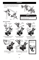
Refer to Figure 7 below to identify your “Chute Control
Style” and continue to the “Assembly” instructions for
your specific style on pages 8-13.
Chute Control Styles
Side Mounted Chute Rotation Control
w/ Manual Pitch on page 8
Chute Control
Rod
Chute
Assembly
Chute Control
Rod
*
Chute
Assembly
Overhead Chute Rotation Control
w/ Manual Pitch on page 8
2-Way & 4-Way
Chute Control
*
Chute
Assembly
Chute
Control Rod
Overhead Chute Rotation Control
w/ 2-Way Pitch or 4-Way Pitch &
Rotation Control on page 9
Overhead Chute Control (Flex Shaft)
w/ Steel Chute & 2-Way Pitch Control
on page 11
Chute Assembly
Chute Control
(Flex Shaft)
Overhead Chute Rotation Control w/ 4-Way
Electric Pitch & Rotation Control on page
12
Electric Chute
Control
Chute Control
Rods
*
Chute
Assembly
*
NOTE: This model may
be equipped with a
metal chute assembly.
Figure 7