® OWNER’S MANUAL Snow Thrower SAFETY FIRST! Before operating this equipment, read this Owner’s Manual and the separate manual supplied by the engine manufacturer. • • • • • • Safety Assembly Features and Controls Operation Maintenance Parts List Models 42051 - 9.
Table of Contents Dear Owner: Thank you for purchasing this product. The unit was carefully designed and manufactured to provide excellent performance if properly operated and maintained. Review this manual frequently to familiarize yourself with the unit, its features and its safe operation. Be sure that you and any other operators carefully follow the recommended safety practices at all times. Failure to do so could result in personal injury or property damage.
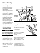
Section 1 Safety Gear Shift Lever SPARK ARRESTER WARNING TO RESIDENTS OF CALIFORNIA AND SEVERAL OTHER STATES Under California law, and under the laws of several other states, you are not permitted to operate an internal combustion engine using hydrocarbon fuels on any forest, brush, hay, grain, or grass covered land; or land covered by any flammable agricultural crop without an engine spark arrester in continuous effective working order.
Section 1: Safety b. The 120V A.C. starter is equipped with a three-wire power cord and plug and is designed to operate on 120V A.C. household current. The starter must be properly grounded at all times to avoid the possibility of injury or death from electrical shock. Determine that your house wiring is a Ground Fault Interrupted (G.F.I.) three-wire grounded system, or ask a licensed electrician if you are not sure. If your house wiring system is not a G.F.I.
Section 1: Safety 22. Be extremely careful when operating on or crossing gravel drives, walks or roads. Stay alert for hidden hazards or traffic. Remove any hearing protection. 23. Do not overload the machine capacity by attempting to clear snow at too fast a rate. 24. After striking a foreign object, stop the engine, remove the wire from the spark plug, thoroughly inspect the unit for any damage, and repair the damage before restarting and operating the unit. 25.
Section 2 Assembly Auger Drive Control Lever WARNING To prevent personal injury or property damage, do not start the engine until all assembly steps are complete and you have read and understand the safety and operating instructions in this manual. NOTE: Left and right sides of the unit are determined from the operator position, facing the direction of forward travel. A. Inspect Unit Inspect the unit and shipping crate for damage immediately after delivery.
Section 2: Assembly D. Install Handlebars 1. Use the four 3/8-16 x 3/4" hex flange screws to attach the handlebars to the sides of the chassis. a. Install a screw in the upper mounting hole (C, Figure 2-3) on each side. Leave screws loose enough to allow handlebar to pivot. b. Install a screw (D) in the lower mounting hole on each side. E E c. Using light pressure, press down on the left side handlebar and tighten the two screws. Repeat on the right side. C 2.
Section 2: Assembly 6. Remove the washer and locknut from the screw (M, Figure 2-4) in the worm gear assembly (L). Position the worm gear assembly on the mounting bracket as follows: a. Engage the worm gear threads 1/2way with the teeth on the flange of the discharge chute base (rotate chute as needed). b. The length of the worm gear should be centered with the teeth on the flange of the discharge chute base. c. Reinstall the washer and locknut on the screw (M) and tighten securely. 7.
Section 2: Assembly Z X T AA Y Figure 2-6 S S V W U U AF Figure 2-5 AF AE AB AA R Figure 2-8 AT AS AC AD AB AG AH Figure 2-7 9
Section 2: Assembly J. Connect Wiring for Handlebar Warmers and Light 1. Gently unwind the electrical wiring harness (A, Figure 2-9) from its shipping position and route it back toward the right-side handlebar. 2. Without over-stretching the wiring harness, loop it up and around the handlebar as shown in Figure 2-9. 3. Connect the double-stranded black and red wires leading from each handlebar to the matching wires leading from the wiring harness. The plastic connectors can only be plugged in one way. 4.
Section 3 Features and Controls WARNING Before operating your machine, carefully read and understand all safety, controls, and operating instructions in this manual, the separate Engine Owner’s Manual and on the decals on the machine. Failure to follow these instructions can result in serious personal injury. IMPORTANT: Refer to the separate Engine Owner’s Manual for detailed information about the controls on the engine. Wheel Drive Control Lever (A, Fig.
Section 4 Operation PRE-OPERATION CHECKLIST Perform the following checks with the engine stopped and the spark plug wire disconnected from the spark plug. 1. Review Section 1: Safety and Section 3: Features and Controls in this manual. 2. Check for loose or missing hardware. Tighten or replace as needed. 3. Visually check inside the collector (auger/impeller) housing and the discharge chute and remove any debris. CAUTION Do not start engine until engine crankcase has been filled with oil.
Section 4: Operation 7. Push the Primer Button (O, Figure 4-2) three times (cover hole in center of bulb when pushing). F E H G 8. To start engine with recoil starter: a. Before pulling recoil starter (N, Figure 4-2), be sure there are no obstacles behind you. D b. Pull recoil starter handle rapidly to overcome engine compression, prevent kick-back and start engine. Maintain control of rope so it slowly returns into the starter mechanism. Repeat pulling until engine starts.
Section 4: Operation AUGER DRIVE ENGAGEMENT WARNING Stop the engine and remove the spark plug wire from the spark plug before removing any debris from the collector (auger/impeller) housing. AUGER DRIVE/WHEEL DRIVE INTERLOCK FEATURE 1. Remove any debris from inside the collector (auger/impeller) housing. 2. Adjust the discharge chute deflector cap (D, Figure 4-3) angle with adjustment lever.
Section 4: Operation WARNING As you turn, rotate the discharge chute so that the snow is always thrown in this direction. ➡ Do not use your hands or feet to dislodge snow from inside the collector (auger/impeller) housing or the discharge chute. Any contact with the moving parts will cause serious injury. Stop the engine and remove the spark plug wire from the spark plug and use a long (at least 3-feet [100CM] long) wooden stick to unclog these areas.
Section 5 Maintenance WARNING Moving parts on the unit can cause serious personal injury. Shut off the engine, let all moving parts stop completely, disconnect the spark plug wire and prevent it from touching the spark plug before performing any maintenance or service procedures. ENGINE MAINTENANCE IMPORTANT: Refer to the Engine Owner’s Manual for complete engine maintenance information. Engine Oil • Check the engine oil level each time before starting the unit and after each 5 hours of operation.
Section 5: Maintenance WARNING Before inspecting, cleaning or servicing the machine, shut off engine, wait for all moving parts to come to a complete stop, disconnect spark plug wire and move wire away from spark plug. Failure to follow these instructions can result in serious personal injury or property damage. X AC P R S A T G Figure 5-2 AB J B K J E F Figure 5-1 H Figure 5-3 4. Squeeze wheel drive control lever (X, Figure 5-1) against handlebar.
Section 5: Maintenance WARNING Before inspecting, cleaning or servicing the machine, shut off engine, wait for all moving parts to come to a complete stop, disconnect spark plug wire and move wire away from spark plug. Failure to follow these instructions can result in serious personal injury or property damage. AC M BA BB 8. If the auger drive belt(s) have been replaced, then perform the Auger Drive Belt Adjustment as described in this section. 9. Reinstall the belt cover.
Section 5: Maintenance WARNING Before inspecting, cleaning or servicing the machine, shut off engine, wait for all moving parts to come to a complete stop, disconnect spark plug wire and move wire away from spark plug. Failure to follow these instructions can result in serious personal injury or property damage. The spring length should now measure 9/16" – 11/16" (14–17mm) longer than the measurement taken in Step 4.
Section 5: Maintenance WARNING Before inspecting, cleaning or servicing the machine, shut off engine, wait for all moving parts to come to a complete stop, disconnect spark plug wire and move wire away from spark plug. Failure to follow these instructions can result in serious personal injury or property damage. AV C N E D ZZ Figure 5-10 To adjust brake arm: 1. With engine stopped and spark plug wire disconnected, remove screws and washers (AB, Figure 5-1) and remove belt cover from unit. 2.
Section 5: Maintenance WARNING Before inspecting, cleaning or servicing the machine, shut off engine, wait for all moving parts to come to a complete stop, disconnect spark plug wire and move wire away from spark plug. Failure to follow these instructions can result in serious personal injury or property damage. TROUBLESHOOTING TROUBLE Engine won’t start POSSIBLE PROBLEM SOLUTION 1. Choke knob in incorrect position 1. Move choke knob to CHOKE position 2.
Section 5: Maintenance WARNING Before inspecting, cleaning or servicing the machine, shut off engine, wait for all moving parts to come to a complete stop, disconnect spark plug wire and move wire away from spark plug. Failure to follow these instructions can result in serious personal injury or property damage. TROUBLESHOOTING (continued) TROUBLE Auger drive control lever does not engage auger drive POSSIBLE PROBLEM 1. Broken square key on engine drive pulley 1. Replace key 2.
Section 5: Maintenance WARNING Before inspecting, cleaning or servicing the machine, shut off engine, wait for all moving parts to come to a complete stop, disconnect spark plug wire and move wire away from spark plug. Failure to follow these instructions can result in serious personal injury or property damage. REQUIRED MAINTENANCE SCHEDULE This table describes service guidelines only and does not provide complete service information.
Specifications, Optional Kits and Accessories SPECIFICATIONS/OPTIONAL KITS AND ACCESSORIES Specifications Below is a list of specifications for your snow thrower. The information is the most current at the time this manual was printed. Engine Model . . . . . . . . . . . . . . . . . . . . . . . . . . . . . . . . . . . . . . . . . . . . . . . . . . . . . . . . . . . . Engine Type . . . . . . . . . . . . . . . . . . . . . . . . . . . . . . . . . . . . . . . . . . . . . . . . . . . . . . . . . . . . . 9.
Parts List Models 42051 & 42052 DRAWING NO. 1 19 18 5 1 8 2 23 3 11 4 15 14 3 16 25 24 14 13 9 22 15 12 20 6 27 22 26 8 13 17 12 7 13 13 12 Ref. # 1 2 3 4 5 6 7 8 9 11 12 13 14 15 Part # 1185224 1185374 1185841 1185431 1739790 1185842 1118726 1773207 1773170001 1735894001 1741832 1100241 1185728 1185815 12 Description Oil Seal.........................................................1 Needle Bearing ............................................ 1 Thrust Race .........................
Parts List Models 42051 & 42052 DRAWING NO.
Parts List Models 42051 & 42052 Ref.
Parts List Models 42051 & 42052 DRAWING NO.
Parts List Models 42051 & 42052 Ref.
Parts List Models 42051 & 42052 DRAWING NO.
Parts List Models 42051 & 42052 Ref.
CUSTOMER SERVICE INFORMATION Owner Registration Card Please fill out and mail the enclosed owner registration card. The purpose of this card is to register each unit at the factory so that we can provide you with warranty benefits and informational bulletins. Customer Service and Technical Service If you have questions or problems with the unit, contact your local dealer or the Factory. (When calling or writing, provide the Model/Serial Numbers of the unit.