Safe Operation Practices • Set-Up • Operation • Maintenance • Service • Troubleshooting • Warranty Operator’s Manual Two-Stage Snow Thrower — Storm 5024 WARNING READ AND FOLLOW ALL SAFETY RULES AND INSTRUCTIONS IN THIS MANUAL BEFORE ATTEMPTING TO OPERATE THIS MACHINE. FAILURE TO COMPLY WITH THESE INSTRUCTIONS MAY RESULT IN PERSONAL INJURY. TROY-BILT LLC, P.O. BOX 361131 CLEVELAND, OHIO 44136-0019 Printed In USA Form No.
1 To The Owner Thank You Thank you for purchasing a Snow Thrower manufactured by Troy-Bilt LLC. It was carefully engineered to provide excellent performance when properly operated and maintained. Please read this entire manual prior to operating the equipment. It instructs you how to safely and easily set up, operate and maintain your machine. Please be sure that you, and any other persons who will operate the machine, carefully follow the recommended safety practices at all times.
Important Safe Operation Practices 2 WARNING! This symbol points out important safety instructions which, if not followed, could endanger the personal safety and/or property of yourself and others. Read and follow all instructions in this manual before attempting to operate this machine. Failure to comply with these instructions may result in personal injury. When you see this symbol.
Safe Handling of Gasoline 5. To avoid personal injury or property damage use extreme care in handling gasoline. Gasoline is extremely flammable and the vapors are explosive. Serious personal injury can occur when gasoline is spilled on yourself or your clothes which can ignite. Wash your skin and change clothes immediately. Never run an engine indoors or in a poorly ventilated area. Engine exhaust contains carbon monoxide, an odorless and deadly gas. 6.
Maintenance & Storage Do not modify engine 1. Never tamper with safety devices. Check their proper operation regularly. Refer to the maintenance and adjustment sections of this manual. 2. Before cleaning, repairing, or inspecting machine disengage all control levers and stop the engine. Wait until the auger/impeller come to a complete stop. Disconnect the spark plug wire and ground against the engine to prevent unintended starting. To avoid serious injury or death, do not modify engine in any way.
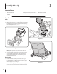
3 Assembly & Set-Up Contents of Carton • One Snow Thrower • Two Replacement Auger Shear Pins • One Snow Thrower Operator’s Manual • One Product Registration Card • One Chute Assembly Assembly Handle 1. Place the shift lever in the forward-6 position. 2. Observe the lower rear area of the snow thrower to be sure both cables are aligned with roller guides before pivoting the handle upward. See Fig. 3-1.
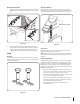
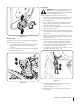
Chute Directional Control Chute Clean-Out Tool 1. The chute clean-out tool is fastened to the top of the auger housing with a mounting clip and a cable tie at the factory. Cut the cable tie before operating the snow thrower. See Fig. 3-6. Remove the plastic cap (if present), flat washer and hairpin clip from the end of the chute directional control. See Fig. 3-4. A Chute Clean-out Tool B Figure 3-4 2.
Adding Fuel Warning! Use extreme care when handling gasoline. Gasoline is extremely flammable and the vapors are explosive. Never fuel the machine indoors or while the engine is hot or running. Extinguish cigarettes, cigars, pipes and other sources of ignition. WARNING! Always keep hands and feet clear of equipment moving parts. Do not use a pressurized starting fluid. Vapors are flammable. 1. Clean around fuel fill before removing cap to fuel. 2. A fuel level indicator is located in the fuel tank.
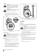
Auger Control Warning! Prior to operating your snow thrower, carefully read and follow all instructions below. Perform all adjustments to verify your snow thrower is operating safely and properly. Check the adjustment of the auger control as follows: Figure 3-9 Chute Assembly The distance snow is thrown can be adjusted by changing the angle of the chute assembly. To do so: 1. Stop the engine by removing the ignition key and loosen the plastic knob found on the left side of the chute assembly. 2.
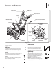
4 Controls and Features Shift Lever Drive Control Auger Control Gas Cap Chute Assembly Oil Fill Chute Directional Control Clean Out Tool Muffler Recoil Starter Handle Primer Ignition Key Throttle Control Choke Control Augers Skid Shoe Oil Drain Electric Outlet Figure 4-1 Snow thrower controls and features are described below and illustrated in Fig. 4-1. Shift Lever The shift lever is located in the right side of the handle panel and is used to determine ground speed and direction of travel.
Throttle Control Auger Control The throttle control is located on the rear of the engine. It regulates the speed of the engine and will shut off the engine when moved into the STOP position. Primer Pressing the primer forces fuel directly into the engine’s carburetor to aid in coldweather starting. Oil Fill Engine oil level can be checked and oil added through the oil fill. Oil Drain Engine oil can be drained through the oil drain. The auger control is located on the left handle.
Chute Directional Control Chute Clean-Out Tool Warning! Never use your hands to clear a clogged chute assembly. Shut off engine and remain behind handles until all moving parts have stopped before unclogging. The chute clean-out tool is conveniently fastened to the rear of the auger housing with a mounting clip.
5 Operation Starting the Engine 3. WARNING! Always keep hands and feet clear of moving parts. Do not use a pressurized starting fluid. Vapors are flammable. Plug the extension cord into the electric outlet located on the engine. Plug the other end of extension cord into a three-prong 120-volt, grounded, AC outlet in a wellventilated area. See Fig. 5-2. NOTE: Allow the engine to warm up for a few minutes after starting. The engine will not develop full power until it reaches operating temperatures.
Recoil Starter Caution! Do not pull the starter handle while the engine running. WARNING: To avoid unsupervised engine operation, never leave the engine unattended while running. Turn the engine off after use and remove ignition key 1. Insert ignition key fully into slot, Figure 5-5. Make sure it snaps into place. DO NOT turn ignition key. The engine cannot start unless the key is inserted into ignition switch. 2. Move throttle control to FAST (rabbit) position. 3.
6 Maintenance & Adjustments Maintenance Lubrication Engine Gear Shaft Refer to the Engine Maintenance section. The gear (hex) shaft should be lubricated at least once a season or after every twenty-five (25) hours of operation. Shave Plate and Skid Shoes The shave plate and skid shoes on the bottom of the snow thrower are subject to wear. They should be checked periodically and replaced when necessary. 1. Carefully pivot the snow thrower up and forward so that it rests on the auger housing. 2.
Auger Shaft Adjustments At least once a season, remove the shear pins from the auger shaft. Spray lubricant inside the shaft and around the spacers and the flange bearings found at either end of the shaft. See Fig. 6-3. Shift Cable If the full range of speeds (forward and reverse) cannot be achieved, refer to the figures to the right and adjust the shift cable as follows: 1. Place the shift lever in the fastest forward speed position. 2. Loosen the hex nut on the shift cable index bracket. See Fig.
Drive Control Chute Bracket Adjustment When the drive control is released and in the disengaged “up” position, the cable should have very little slack. It should NOT be tight. If the spiral at the bottom of the chute directional control is not fully engaging with the chute assembly, the chute bracket can be adjusted. To do so: NOTE: If excessive slack is present in the drive cable or if the snow thrower’s drive is disengaging intermittently during operation, the cable may be in need of adjustment. 1.
7 Engine Maintenance WARNING! To prevent accidental start-up, shut off the engine and remove the ignition key before performing any type of engine maintenance. Periodic inspection and adjustment of the engine is essential if high level performance is to be maintained. Regular maintenance will also ensure a long service life. The required service intervals and the type of maintenance to be performed are described in the table below. Follow the hourly or calendar intervals, whichever occur first.
Spark Plug 4. Check that the spark plug washer is in good condition and thread the spark plug in by hand to prevent crossthreading. 5. After the spark plug is seated, tighten with a spark plug wrench to compress the washer. WARNING! DO NOT check for spark with spark plug removed. DO NOT crank engine with spark plug removed. NOTE: When installing a new spark plug, tighten 1⁄2-turn after the spark plug seats to compress the washer.
8 Service Belt Replacement 3. Auger Belt Carefully pivot the snow thrower up and forward so that it rests on the auger housing. 4. Remove the frame cover from the underside of the snow thrower by removing four self-tapping screws which secure it. See Fig 7-3. To remove and replace your snow thrower’s auger belt, proceed as follows: 1. To prevent spillage, place a piece of plastic wrap under the gas cap and tighten securely. 2.
6. Remove the belt from around the auger pulley, and slip the belt between the support bracket and the auger pulley. See Fig. 7-5. Drive Belt To remove and replace your snow thrower’s drive belt, proceed as follows: 1. Place a piece of plastic under the gas cap. 2. Remove the plastic belt cover on the front of the engine by removing the two self-tapping screws. Refer to Fig. 7-1. 3. Remove the belt as follows. See Fig. 7-6.: a. Roll the auger belt off the engine pulley. b.
6. Slip the drive belt off the pulley and between friction wheel and friction wheel disc. See Fig. 7-7. Friction Wheel Removal If the snow thrower fails to drive with the drive control engaged, and performing the drive control cable adjustment fails to correct the problem, the friction wheel may need to be replaced. Follow the instructions below. Examine the friction wheel for signs of wear or cracking and replace if necessary: 1. Place a piece of plastic under the gas cap. 2.
5. Carefully remove the hex nut which secures the hex shaft to the snow thrower frame and lightly tap the shaft’s end to dislodge the ball bearing from the right side of the frame. See Fig. 7-9. NOTE: Be careful not to damage the threads on the shaft. Follow the previous steps in reverse order to reassemble components. If you’re disassembling the friction wheel and replacing only the rubber ring, proceed as follows: 1. Figure 7-11 Figure 7-9 6.
9 Troubleshooting Problem Engine fails to start Cause 1. Choke not in ON position. 1. Move choke to ON position. 2. Spark plug wire disconnected. 2. Connect wire to spark plug. 3. Fuel tank empty or stale fuel. 3. Fill tank with clean, fresh gasoline. 4. Engine not primed. 4. Prime engine as instructed in “Operating Your Snow Thrower”. 5. Faulty spark plug. 5. Clean, adjust gap, or replace. 6. Safety key not in ignition on engine. 6. Insert key fully into the switch. 1.
10 Replacement Parts Component Part Number and Description 929-0071 Extention Cord, 110V 954-04050 754-0367 Auger Drive Belt Wheel Drive Belt 684-04153 935-04054 Friction Wheel Assembly Friction Wheel Rubber 784-5580 Slide Shoe, Standard 731-2643 Chute Clean-out Tool 790-00120 Shave Plate, 24” 751-10630 Key 751-10292 Spark Plug Phone (800) 828-5500 to order replacement parts or a complete Parts Manual (have your full model number and serial number ready).
Troy-Bilt LLC (Troy-Bilt), The United States Environment Protection Agency (U. S. EPA) Emission Control System Warranty Statement (Owner’s Defect Warranty Rights and Obligations) The U. S. EPA and Troy-Bilt are pleased to explain the emissions control system warranty on your model year 2005 and later small off-road engine. New small off-road engines must be designed, built and equipped to meet the stringent anti-smog standards.
(7) The engine manufacturer is liable for damages to other engine components proximately caused by a failure under warranty of any warranted part. (8) Throughout the engine’s warranty period defined in Subsection (a)(2), Troy-Bilt will maintain a supply of warranted parts sufficient to meet the expected demand for such parts. (9) Any replacement part may be used in the performance of any warranty maintenance or repairs and must be provided without charge to the owner.
MANUFACTURER’S LIMITED WARRANTY FOR The limited warranty set forth below is given by Troy-Bilt LLC with respect to new merchandise purchased and used in the United States and/or its territories and possessions, and by MTD Products Limited with respect to new merchandise purchased and used in Canada and/or its territories and possessions (either entity respectively, “Troy-Bilt”). c. Service completed by someone other than an authorized service dealer.
Medidas importantes de seguridad • Configuración • Funcionamiento • Mantenimiento • Servicio • Solución de problemas • Garantía Manual del Operador Máquina quitanieve de dos etapas — Storm 5024 ADVERTENCIA LEA Y SIGA TODAS LAS INSTRUCCIONES DE ESTE MANUAL ANTES DE PONER EN FUNCIONAMIENTO ESTA MÁQUINA. SI NO RESPETA ESTAS INSTRUCCIONES PUEDE PROVOCAR LESIONES PERSONALES. TROY-BILT LLC, P.O. BOX 361131 CLEVELAND, OHIO 44136-0019 Impreso en Estados Unidos de América Formulario No.
1 Al Propietario Gracias Gracias por comprar una máquina quitanieve fabricada por Troy-Bilt LLC. La misma ha sido diseñada cuidadosamente para brindar excelente rendimiento si se la opera y mantiene correctamente. Por favor lea todo este manual antes de operar el equipo. Le indica cómo configurar, operar y mantener la máquina con seguridad y fácilmente.
2 Medidas importantes de seguridad ADVERTENCIA: La presencia de este símbolo indica que se trata de instrucciones importantes de seguridad que se deben respetar para evitar poner en peligro su seguridad personal y/o material y la de otras personas. Lea y siga todas las instrucciones de este manual antes de poner en funcionamiento esta máquina. Si no respeta estas instrucciones puede provocar lesiones personales.
Manejo seguro de la gasolina Para evitar lesiones personales o daños materiales tenga mucho cuidado cuando trabaje con gasolina. La gasolina es sumamente inflamable y sus vapores pueden causar explosiones. Si se derrama gasolina encima o sobre la ropa se puede lesionar gravemente ya que se puede incendiar. Lávese la piel y cámbiese de ropa de inmediato. a. b. Utilice sólo los recipientes para gasolina autorizados. Apague todos los cigarrillos, cigarros, pipas y otras fuentes de combustión. c.
Mantenimiento y Almacenamiento No modifique el motor 1. Nunca altere los dispositivos de seguridad. Controle periódicamente que funcionen correctamente. Remítase a las secciones de mantenimiento y ajuste de este manual. 2. Antes de realizar la limpieza, reparar o revisar la máquina, desengrane todas las palancas de control y detenga el motor. Espere a que la barrena / impulsor se detenga por completo.
3 Montaje y Configuración Contenido de la caja • Una máquina quitanieve • Un Manual del Operador de la Máquina Quitanieve • Dos pasadores de cuchilla de barrena de repuesto • Una tarjeta para registrar el producto Montaje Manija 1. Coloque la palanca de cambios en la posición de avance (F) 6. 2. Observe el área inferior trasera de la máquina quitanieve para asegurarse de que ambos cables estén alineados con las guías rotatorias antes de girar la manija hacia arriba. Vea la Fig. 3-1.
Control direccional del canal Herramienta de limpieza del canal 1. 1. Quite la tapa plástica (si presente), arandela y horquilla planas sujetan del fin del tobogán el control direccional. Vea la Fig. 3-4. A La herramienta de limpieza del canal viene de fábrica ajustada a la parte superior de la caja de la barrena con un pasador de ensamblado y una unión de cable. Corte la unión de cable antes de operar la máquina quitanieve. Vea la Fig. 3-6. B Figura 3-4 2.
Carga de combustible ¡ADVERTENCIA! Tenga mucho cuidado al trabajar con gasolina. La gasolina es sumamente inflamable y sus vapores pueden causar explosiones. Nunca agregue combustible a la máquina en interiores ni mientras el motor está caliente o en funcionamiento. Apague cigarrillos, cigarros, pipas y otras fuentes de combustión. ¡ADVERTENCIA! Siempre mantenga las manos y los pies alejados de las piezas móviles del equipo. No utilice fluidos presurizados para arrancar. Los vapores son inflamables. 1.
Control de la barrena ¡Advertencia! Antes de operar su máquina quitanieve, lea atentamente y cumpla todas las instrucciones que aparecen a continuación. Realice todos los ajustes para verificar que la máquina está operando con seguridad y correctamente. Compruebe el ajuste del control de la barrena de la siguiente forma: 1. Cuando se suelta el control de la barrena y está en posición desengranada arriba, el cable debe tener muy poco juego. NO debe estar tenso. 2.
4 Controles y Características Palanca de Cambios Control de Transmisión Control de la Barrena Tapón de combustible Montaje del canal Llenado de aceite Control direccional del canal Herramienta de limpieza del canal Silenciador Manija del arrancador de retroceso Cebador Llave de encendido Control del regulador Control del cebador Barrenas Zapatas antideslizantes Llene del aceite Botón del arrancador eléctrico Salida del arrancador eléctrico Figura 4-1 Los controles y características de la máqu
Control del regulador Control de la barrena El control del regulador está ubicado en la parte trasera del motor. Regula la velocidad del motor, y lo apaga cuando se lo coloca en la posición STOP (detención). Cebador Al presionar el cebador se envía combustible directamente al carburador del motor para ayudar al encendido cuando el clima es frío. Llenado de aceite Es posible controlar el nivel de aceite del motor, así como también agregar aceite, a través del llenado de aceite.
Control direccional del canal Control direccional del canal Descarga La Izquierda Herramienta de limpieza del canal ¡Advertencia! Nunca use las manos para liberar un montaje de canal tapado. Antes de destaparlo, apague el motor y permanezca detrás de las manijas hasta que todas las partes móviles se hayan detenido.
5 Funcionamiento Encendido del motor 1. Conecte el cable de la bujía a la misma. Compruebe que el lazo de metal del extremo de la bujía esté bien ajustado (dentro de la manga de goma) sobre la punta metálica de la bujía. 2. Asegúrese de que el control de la barrena y el control de la transmisión estén en posición desengranada (sin presionar). 3. Mueva el control del regulador a la posición FAST (rápido). Inserte la llave de encendido en la ranura. Asegúrese de que entre a presión en su lugar.
Procedimiento para engranar la transmisión 1. Con el control del regulador en posición rápida (dibujo de un conejo), mueva la palanca de cambios a una de las seis posiciones de avance (F) o de las dos posiciones de reversa (R). Seleccione la velocidad adecuada para el estado de la nieve existente y una velocidad con la que se sienta cómodo. 2. Apriete el control de la transmisión contra la manija y la máquina quitanieve se moverá. Suéltelo y se detendrá el movimiento de la transmisión.
6 Mantenimiento y Ajustes Mantenimiento Lubricación Motor Eje de engranaje Consulte el sección de Motor Mantenimiento para ver el mantenimiento del motor. El eje de engranaje (hexagonal) se debe lubricar al menos una vez por temporada o tras cada 25 horas de operación. Placa de raspado y zapatas antideslizantes 1. La placa de raspado y las zapatas antideslizantes ubicadas en la base de la máquina quitanieve están sujetas a desgaste.
Eje de la barrena Ajustes Al menos una vez por temporada, quite los pasadores de cuchilla del eje de la barrena. Rocíe lubricante en el interior del eje y alrededor de los separadores y los cojinetes bridados que se encuentran en ambos extremos del eje. Cable de cambios Vea la Fig. 6-3. Si no se puede lograr toda la gama de velocidades (avance y retroceso), consulte las figuras de la derecha y ajuste el cable de cambios de la siguiente forma: 1.
Control de la transmisión Ajuste del soporte del canal Cuando se suelta el control de la transmisión y está en posición desenganchada arriba, el cable debe tener muy poco juego. NO debe estar tenso. Si el espiral en el fondo del control direccional del canal no está enganchando completamente con el montaje del canal , el soporte del canal puede ser ajustado.
7 Mantenimiento del motor ¡ADVERTENCIA! Para evitar el arranque accidental, apague el motor y retire la llave de encendido antes de realizar cualquier tipo de mantenimiento del motor. Calendario de mantenimiento Tareas Primeras 5 horas La inspección y los ajustes periódicos del motor son esenciales si se desea mantener un alto nivel de rendimiento. El mantenimiento regular también garantizará una prolongada vida útil del motor.
Bujía de encendido 4. Verifique que la arandela de la bujía esté en buenas condiciones y enrósquela manualmente para no estropear la rosca. 5. Una vez que la bujía esté colocada, apriétela con una llave para comprimir la arandela. ¡ADVERTENCIA! NO pruebe la chispa si no está la bujía de encendido. NO dé arranque al motor si no está la bujía de encendido. ¡ADVERTENCIA! Si el motor ha estado funcionando, el silenciador estará muy caliente. Tenga cuidado de no tocar el silenciador.
8 Servicio Cambio de correa 3. Gire con cuidado la máquina quitanieve hacia arriba y hacia delante de manera que quede apoyada sobre la caja de la barrena. 4. Saque la cubierta del marco desde debajo de la máquina quitanieve retirando los cuatro tornillos autorroscantes que la aseguran. Vea la Fig. 7-3. Correa de la barrena Para retirar y reemplazar la correa de la barrena de su máquina quitanieve, proceda como se indica a continuación: 1.
6. Retire la correa de alrededor de la polea de la barrena y deslice la misma entre la ménsula de soporte y la polea de la barrena. Vea la Fig. 7-5. 3. Quite la correa como sigue: Vea la Fig. 7-6.: a. Saque la correa de la barrena de la polea del motor. b. Use una llave para girar la polea loca hacia la derecha. c. Levante la correa de la barrena para sacarla de la polea del motor. Figura 7-5 7. Para realizar el reensamblado de la correa de la barrena siga las instrucciones en orden inverso.
6. Deslice la correa de la transmisión fuera de la polea y de entre la rueda de fricción y el disco de la rueda de fricción. Extracción de la rueda de fricción Si la máquina quitanieve no se mueve cuando el control de la transmisión está engranado, y si al realizar el ajuste del cable de control de la transmisión el problema no se corrige, es posible que deba reemplazar la rueda de fricción. Siga las instrucciones que aparecen a continuación.
5. Retire con cuidado la tuerca hexagonal y la arandela que sujetan el eje hexagonal al marco de la máquina quitanieve, y golpee suavemente el extremo del eje para desplazar el cojinete de bolas del lado derecho del marco. Vea la Fig. 7-9. NOTA: Tenga cuidado de no dañar las roscas del eje. Para reensamblar los componentes siga los pasos anteriores en orden inverso. Si está desmontando la rueda de fricción para reemplazar únicamente el anillo de goma, proceda como se indica a continuación: 1.
9 Solución de Problemas Problema Causa Solución 1. El control del cebador no está en la posición ON (encendido). 1. Ponga el control del cebador en la posición ON (encendido). 2. Se ha desconectado el cable de la bujía. 2. Conecte el cable a la bujía. 3. El depósito de combustible está vacío o el combustible se ha echado a perder. 3. Llene el tanque con gasolina limpia y fresca. 4. El motor no está cebado. 4. Cebe el motor tal como se explicó en la sección “Funcionamiento. 5.
10 Piezas de Reemplazo Componente Número de pieza y Descripción 929-0071 Cordón prolongador, 110V 954-04050 754-0367 Correa de transmisión de la barrena Correa de transmisión de la rueda 684-04153 935-04054 Montaje de rueda de fricción Goma de la rueda de fricción 738-04124A 714-04040 Pasador de cuchilla, 1,50 Pasador de chaveta con unión curva 784-5580 Zapata antideslizante, Estándar 731-2643 Herramienta de limpieza del canal 790-00120 Placa de raspado, 24” 751-10630 Llave 751-10292 Bují
Troy-Bilt LLC (Troy-Bilt), la Agencia de Protección Medioambiental de Estados Unidos (U. S. EPA) Declaración de Garantía del Sistema de Control de Emisiones (Derechos y obligaciones del propietario según la garantía contra defectos) La U. S. EPA y Troy-Bilt se complacen en explicar la garantía del sistema de control de emisiones de su motor para equipo todo terreno, modelo, año 2005 y versiones posteriores.
(4) La reparación o el reemplazo de cualquier pieza garantizada de conformidad con las disposiciones de la garantía que aquí se estipula se debe realizar en un centro de garantía sin costo alguno para el propietario. (5) Sin perjuicio de las disposiciones de la Subsección (4) anterior, los servicios o reparaciones cubiertos por la garantía deben ser suministrados por todos los centros de distribución de Troy-Bilt que tengan la franquicia para realizar reparaciones y mantenimiento a los motores en cuestión.
GARANTÍA LIMITADA DEL FABRICANTE PARA La siguiente garantía limitada es otorgada por Troy-Bilt LLC con respecto a nuevos productos adquiridos y utilizados en Estados Unidos y/o sus territorios y posesiones, y por MTD Products Limited con respecto a nuevos productos adquiridos y utilizados en Canadá y/o sus territorios y posesiones (cualquiera de las dos entidades, respectivamente, “Troy-Bilt”).