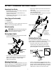
Operator’s Manual Single Stage Snow Thrower Models 521 & 721 IMPORTANT: Read safety rules and instructions carefully before operating equipment. Warning: This unit is equipped with an internal combustion engine and should not be used on or near any unimproved forestcovered, brush-covered or grass-covered land unless the engine’s exhaust system is equipped with a spark arrester meeting applicable local or state laws (if any).
TABLE OF CONTENTS Content Page Important Safe Operation Practices .................................................................................. 3 Assembling Your Snow Thrower ....................................................................................... 5 Know Your Snow Thrower................................................................................................. 6 Operating Your Snow Thrower ..........................................................................................
SECTION 1: IMPORTANT SAFE OPERATION PRACTICES WARNING: This symbol points out important safety instructions which, if not followed, could endanger the personal safety and/or property of yourself and others. Read and follow all instructions in this manual before attempting to operate this machine. Failure to comply with these instructions may result in personal injury. When you see this symbol—heed its warning.
. 5. 6. 7. 8. 9. 10. 11. 12. 13. 14. 15. 16. 17. 18. 19. 20. Maintenance & Storage Never operate with a missing or damaged discharge chute. Keep all safety devices in place and working. Never run an engine indoors or in a poorly ventilated area. Engine exhaust contains carbon monoxide, an odorless and deadly gas. Do not operate machine while under the influence of alcohol or drugs. Muffler and engine become hot and can cause a burn. Do not touch.
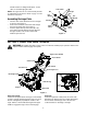
SECTION 2: ASSEMBLING YOUR SNOW THROWER Unpacking From Carton • • • • Cut along corners of the carton and lay it down flat. Remove packing material. Remove any loose parts included with unit (i.e., operator’s manual, etc.). Roll unit out of carton. Check carton thoroughly for any remaining loose part. • • Remove the hairpin clip from the end of the lower chute crank. Insert the upper chute crank into the lower chute crank and align the holes.
handle. Hold the “Z” fitting with the pliers, not the cable, to avoid damaging the cable. Lower Chute Nut NOTE: The upper hole in the control handle provides for adjustment in belt tension. Refer to page 9 of this manual for instructions. Carriage Bolt Flat Washer Flat Washer Assembling Discharge Chute • • • Hex Bolt Turn the chute crank until the chute faces straight to the front. See Figure 4 . Remove the hand knob, flat washer and carriage bolt from the upper chute. See Figure 4.
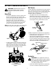
Discharge Chute Ignition Key The angle of the discharge chute controls the distance that the snow is thrown. Tilt the discharge chute up for greater distance; tilt down for less distance. Loosen the hand knob on the side of the discharge chute to adjust. Tilt the chute to the desired position, and tighten the knob. Used to start engine. Put key in “ON” position to start for both electric and recoil start engines. Follow starting instructions given in the next section.
• • • • • • If you have a grounded three-prong receptacle, proceed as follows. Rotate choke lever to FULL position. Connect power cord to switch box on dash panel. Plug the other end of power cord into a three-prong 120-volt, grounded, AC receptacle. Push starter button to crank engine. As you crank the engine, move choke lever to FULL choke position. When engine starts, release starter button, and move choke gradually to OFF. If engine falters, move choke immediately to FULL and then gradually to OFF.
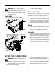
SECTION 5: MAKING ADJUSTMENTS Belt Tension WARNING: NEVER attempt to make any Periodic adjustment of the belt tension may be required due to normal stretch and wear on the belt. Adjust the belt tension if the augers seem to hesitate while turning although engine maintains the same speed. Follow instructions below for adjustment: adjustments while the engine is running, except where specified in the operator’s manual.
SECTION 6: MAINTAINING YOUR SNOW THROWER • WARNING: Before servicing, repairing, or • inspecting, disengage all clutch levers and stop engine. Wait until all moving parts have come to a complete stop. Disconnect spark plug wire and ground it against the engine to prevent unintended starting. Push down on the idler pulley and slip the belt off the auger pulley. See Figure 13. Reassemble new belt. Reinstall the belt cover.
SECTION 8: TROUBLESHOOTING GUIDE Problem Cause Remedy Engine fails to start 1. 2. 3. 4. 5. 6. 7. Fuel tank empty, or stale fuel Blocked fuel line Key not in ON position Spark plug wire disconnected Faulty spark plug Engine not primed Engine flooded with excessive priming Engine runs erratic 1. Unit running on choke 2. Fuel line blocked, or stale fuel 1. 2. 3. 4. 5. Fill tank with clean fresh gasoline. Clean fuel line Insert key and turn to ON position Connect wire to spark plug.
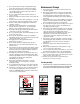
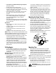
SECTION 9: PARTS LIST FOR MODELS 521 AND 721 15 9 6 21 6 17 14 6 21 24 21 23 3 1 8 22 10 13 4 2 20 25 16 7 33 11 57 32 35 47 42 12 19 48 45 18 31 44 26 58 11 35 53 41 49 60 36 5 5 42 28 33 27 52 37 29 59 5 54 49 56 40 50 51 35 43 53 38 34 46 55 39 30 12
Models 521 & 721 Ref. No. 1. 2. 3. 4. 5. 6. 7. 8. 9. 10. 11. 12. 13. 14. 15. 16. 17. 18. 19. 20. 21. 22. 23. 24. 25. 26. 27. 28. 29. 30. Part No. Part Description 684-0174 Upper Chute Crank Assemby 684-0177 Lower Chute Crank Assembly 684-0178 Bracket Assembly: Mitten Grip 731-04075 Shroud (Model 521) 731-2569 710-0895 Shroud (Model 721) TT Screw 1/4-15 x 0.75” 710-1003 B Screw #10-16 x 0.625” 710-1882 Hex Fl. Screw 5/16-18 x 1.5” 710-3083 Hex Bolt 5/16-18 x 1.
Models 521 and 721 19 16 24 18 1 15 7 5 11 10 15 8 17 Engine is for reference only and may not resemble the engine on your snow thrower. 9 6 13 25 3 13 23 21 14 3 2 4 22 Ref. No. 1. 2. 3. 4. 5. 6. 7. 8. 9. 10. 11. 13. Part No. 629-0071 Description Extension Cord 710-0157 Hex Bolt 5/16-24 x 0.75” 710-0409 Hex Bolt 5/16-24 x 1.75” 710-0502A TT Sems Screw 710-0751 Hex Screw 1/4-20 x 0.620” 710-1003 B Screw #10-16 x 0.625” 710-3013 Hex Screw 1/4-20 x 0.
Models 521 and 721 Ref. No. 5 9 8 10 3 2 Part No. Description 1. 710-0487 Carriage Screw 5/16-18 x 2.0” 2. 710-1270 Machine Screw 3. 712-0324 Hex Lock Nut 1/4-20 4. 720-0284 Hand Knob w/ Wing Nut 5. 720-0295 Foam Grip 6. 725-0157 Cable Tie 7. 736-0451 Saddle Washer 8. 746-0883 Control Housing 9. 747-0956 Auger Bail 10. 749-0711A Upper Handle: Gull Wing 4 NOTE: For painted parts, please refer to the list of color codes below.
MANUFACTURER’S LIMITED WARRANTY FOR: The limited warranty set forth below is given by Troy-Bilt LLC with respect to new merchandise purchased and used in the United States, its possessions and territories. Troy-Bilt LLC warrants this product against defects for a period of two (2) years commencing on the date of original purchase and will, at its option, repair or replace, free of charge, any part found to be defective in materials or workmanship.