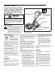
Operator’s Manual Rear-tine Tiller Models 643C — Tuffy® / Bronco CRT 643B, 645A — Super Bronco TM Model 645A Shown IMPORTANT: Read safety rules and instructions carefully before operating equipment. Warning: This unit is equipped with an internal combustion engine and should not be used on or near any unimproved forest-covered, brushcovered or grass-covered land unless the engine’s exhaust system is equipped with a spark arrester meeting applicable local or state laws (if any).
TABLE OF CONTENTS Content Customer Support Safety Assembly Features and Controls Operation Page 2 3 6 10 12 Content Maintenance Off-season Storage Troubleshooting Parts List Warranty Page 17 21 22 24 Back Cover FINDING MODEL NUMBER This Operator’s Manual is an important part of your new tiller. It will help you assemble, prepare and maintain the unit for best performance. Please read and understand what it says.
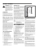
SECTION 1: SAFETY This machine meets voluntary safety standard B71.8 – 1996, which is sponsored by the Outdoor Power Equipment Institute, Inc., and is published by the American National Standards Institute. Forward Clutch Bail Reverse Clutch Control (Models 643B & 645A) WARNING Depth Regulator The engine exhaust from this product contains chemicals known to the State of California to cause cancer, birth defects or other reproductive harm.
5. If the unit should start to vibrate abnormally, stop the engine, disconnect the spark plug wire and prevent it from touching the spark plug, and check immediately for the cause. Vibration is generally a warning of trouble. 6. Stop the engine, disconnect the spark plug wire and prevent it from touching the spark plug, whenever you leave the operating position, before unclogging the tines, or when making any repairs, adjustments or inspections. 7.
Decals Keep the decals clean and legible at all times. Contact your local service dealer or the factory for replacements if any decals are damaged or missing. Reverse Clutch Control Operating Instruction (Models 643B & 645A) Forward Clutch Bail For your safety and the safety of others, various safety and operational decals are located on your unit (see Figure 1-2).
SECTION 2: ASSEMBLY WARNING: To prevent personal injury or property damage, do not start the engine until all assembly steps are complete and you have read and understand the safety and operating instructions in this manual. INTRODUCTION Carefully follow these assembly steps to correctly prepare your tiller for use. It is recommended that you read this Section in its entirety before beginning assembly. NOTE: Various tiller models are presented in this Manual.
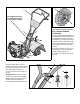
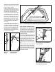
J I K The support brackets must be assembled to the outside of the handlebar assembly. L G Fig. 2-3: Wheel in FREEWHEEL position (wheel drive pin through wheel shaft only). D STEP 4: INSTALL FORWARD CLUTCH CABLE A 1. Carefully unwrap the forward clutch cable (cable without an attached knob) from its shipping position and slide the thin cable wire (M, Fig. 2-4) into the slot in the cable bracket. Push the cable connector (N, Fig.
6 4 5 4. Check for correct tension on the forward drive belt by taking two measurements of the cable spring, as follows: b. Squeeze the Forward Clutch Bail against the handlebar (see Fig. 2-7) and re-measure the spring length. The belt tension is correct if this second measurement is between 1/16" to 3/16" longer than the first measurement. If so, turn the hex nut (Z, Fig. 2-7) tightly against the cable adjuster (X) while preventing the cable adjuster from turning. c.
STEP 6: CHECK TRANSMISSION OIL LEVEL The transmission was filled with gear oil at the factory. However, you should check the gear oil level at this time to make certain it is correct. IMPORTANT: Do not operate the tiller if the gear oil level is low. Doing so will result in severe damage to the transmission components. 1. With the tiller on level ground, pull the Depth Regulator Lever (FF, Fig. 2-10) back and then all the way up until the lowest notch in the lever is engaged. 2.
SECTION 3: FEATURES AND CONTROLS WARNING: Before operating your machine, carefully read and understand all safety, controls and operating instructions in this Manual, the separate Engine Owner’s Manual, and on the decals on the machine. Failure to follow these instructions can result in serious personal injury. Forward Clutch Bail Reverse Clutch Control (Models 643B & 645A) Depth Regulator INTRODUCTION This Section describes the location and function of the controls on your tiller.
WARNING: Use extreme A B Figure 3-3: FREEWHEEL position. WARNING: Before starting engine, be sure that both wheels are in WHEEL DRIVE position. See Wheels Drive Pins for instructions. Engaging the Forward Clutch Bail or Reverse Clutch Control (if equipped) when the wheels are not in WHEEL DRIVE could allow the tines to rapidly propel the tiller forward or backward. Failure to comply could cause loss of tiller control, property damage, or personal injury.
SECTION 4: OPERATION WARNING: Before operating your machine, carefully read and understand all safety (Section 1), controls (Section 3) and operating instructions (Section 4) in this Manual, the separate Engine Owner’s Manual, and on the decals on the machine. Failure to follow these instructions can result in serious personal injury.
Stopping the Engine and Tiller 1. To stop the wheels and tines, release the Forward Clutch Bail (all models) or the Reverse Clutch Control (Models 643B & 645A) — whichever control is in use. 2. To stop the engine, put the ignition switch and/or the throttle control lever in the “OFF” or “STOP” position. OPERATING THE TILLER The following operating instructions provide guidelines to using your tiller effectively and safely.
TILLING TIPS & TECHNIQUES Tilling Depths • This is a CRT (counter-rotating tine) tiller. As the wheels pull forward, the tines rotate backward. This creates an “uppercut” tine action which digs deeply, uprooting soil and weeds. Don’t overload the engine, but dig as deeply as possible on each pass. On later passes, the wheels may tend to spin in the soft dirt. Help them along by lifting up slightly on the handlebar (one hand, palm up, works most easily).
TILLING TIPS & TECHNIQUES (CON’T) Tilling On Slopes Read the following recommendations before tilling on slopes: WARNING: Do not If you must garden on a moderate slope, please follow two very important guidelines: 1. Till only on moderate slopes, never on steep ground where footing is difficult (review safety rules in Section 1: Safety of this manual). 2. We recommend tilling up and down slopes rather than terracing.
TILLING TIPS & TECHNIQUES (CON’T) Terrace Gardening (continued) • To create a terrace, start at the top of the slope and work down. Go back and forth across the first row as shown in Fig. 4-10. • Each succeeding lower terrace is started by walking below the terrace you’re preparing. For added stability of the tiller, always keep the uphill wheel in the soft, newly tilled soil. Do not till the last 12" or more of the downhill outside edge of each terrace.
SECTION 5: MAINTENANCE WARNING: Before TILLER LUBRICATION inspecting, cleaning or servicing the machine, shut off engine, wait for all moving parts to come to a complete stop, disconnect spark plug wire and move wire away from spark plug. Remove ignition key on electric start models. Failure to follow these instructions can result in serious personal injury or property damage. After every 10 operating hours, oil or grease the lubrication points shown in Figure 5-1 and described below.
WARNING: Before inspecting, cleaning or servicing the machine, shut off engine, wait for all moving parts to come to a complete stop, disconnect spark plug wire and move wire away from spark plug. Failure to follow these instructions can result in serious personal injury or property damage. 4. The gear oil level is correct if the gear oil is approximately halfway up the side of the main drive shaft. 5. If the gear oil level is low, add gear oil as described next.
WARNING: Before inspecting, cleaning or servicing the machine, shut off engine, wait for all moving parts to come to a complete stop, disconnect spark plug wire and move wire away from spark plug. Failure to follow these instructions can result in serious personal injury or property damage. b. Unthread the hex nut (C, Figure 5-4) halfway up the adjustment screw (D). c. Unhook the top of the spring from the Forward Clutch Bail. d.
WARNING: Before inspecting, cleaning or servicing the machine, shut off engine, wait for all moving parts to come to a complete stop, disconnect spark plug wire and move wire away from spark plug. Failure to follow these instructions can result in serious personal injury or property damage. FORWARD CLUTCH BAIL ADJUSTMENT If the Forward Clutch Bail does not function properly, first check that the forward drive belt is adjusted properly (see Checking and Adjusting Forward Drive Belt Tension).
WARNING: Before inspecting, cleaning or servicing the machine, shut off engine, wait for all moving parts to come to a complete stop, disconnect spark plug wire and move wire away from spark plug. Failure to follow these instructions can result in serious personal injury or property damage. 3. Clean around the oil dipstick or oil fill tube (whichever applies) to prevent dirt from falling into the crankcase. 4.
WARNING: Before inspecting, cleaning or servicing the machine, shut off engine, wait for all moving parts to come to a complete stop, disconnect spark plug wire and move wire away from spark plug. Failure to follow these instructions can result in serious personal injury or property damage. TROUBLESHOOTING PROBLEM Engine does not start POSSIBLE CAUSE CORRECTION 1. Spark plug wire disconnected. 1. Reconnect wire. 2. Engine Throttle Control Lever incorrectly set. 2. Put lever in START position. 3.
NOTES 23
Models 643C, 643B & 645A 23 27 31 25 34 4 28 29 36 30 22 41 4 4 33 1 A 24 40 26 49 35 32 38 9 20 2 48 12 18 6 42 46 11 9 7 A 39 7 16 21 3 19 10 24 14 6 37 8 5 7 13 17 44 7 43 45 47 39 24 15
MODELS 643C, 643B & 645A REF NO. 1 2 3 4 5 6 7 8 9 10 11 12 13 14 15 16 17 18 19 20 21 22 23 24 25 26 PART NO. 686-04043 686-04041 710-0395 710-0597 710-0599 710-0874 710-3008 712-04063 712-04064 715-0108 732-04320 736-0275 750-04149 750-04160 750-04556 786-04092 786-04098 786-04104 786-04191 786-04290 786-04291 786-04292 710-0106 710-04163 712-3009 712-0121 712-0291 DESCRIPTION Tine Hood Assembly (A) Tine Hood Assembly (B) (C) Hex Screw, 5/16-18 x 2.25 Hex Hd.
MODELS 643C, 643B & 645A 1 REF NO. 2 3 1 2 3 4 5 4 2 5 — PART NO. GW-9517 GW-1714 GW-50043 711-04110 GW-1224-1* GW-1224-2* GW-1224-3* GW-1224-4* GW-1325C DESCRIPTION Snap Ring Bearing, Tapered Roller (with race) Support Washer, Rear Drive Shaft Shim, Rear Bearing Cap, .010" thick Shim, same as above, except .030" thick Shim, same as above, except .005" thick Shim, same as above, except .062" thick Shim Set (Incl.
MODELS 643C, 643B & 645A 8 2 6 3 4 7 FRONT 11 5 10 9 7 4 3 2 REF NO. 2 3 4 5 (A) For Model 643C (B) For Model 643B (C) For Model 645A 6 7 8 9 10 11 PART NO. 1909950 GW-1166-1* GW-1166-2* GW-1166-3* GW-1166-4* GW-1166-5* GW-1086 711-04512 711-04486 GW-9305 GW-1132-2 1904278 711-04078 GW-1104 1916542 DESCRIPTION Retainer, Snap Ring Shim, 0.062" thick Shim, 0.030" thick Shim, 0.015" thick Shim, 0.010" thick Shim, 0.
MODELS 643C, 643B & 645A 40 23 29 45 8 19 27 14 44 13 A 26 36 12 33 48 35 31 46 34 22 30 7 28 21 37 2 32 42 48 A 17 23 15 27 20 39 6 26 5 1 3 23 10 38 1 44 4 18 16 Model 643C 22 43 33 11 24 15 31 35 28 30 37 37 2 9 42 17 99 15 27 18 11 20 43 41 36 32 38 47 6 3 44 28
MODELS 643C, 643B & 645A REF NO. 1 2 3 4 5 6 7 8 9 10 11 12 13 14 15 16 17 18 19 20 21 22 23 24 25 26 PART NO. 736-0159 756-04198 656-04023 656-04005 756-04169 786-04095 754-04090 754-04091 731-05268 732-04289 732-04081 732-04079 786-04068 786-04069 786-04070 748-04087 786-04276 786-04275 710-0672 710-0117 710-0237 710-0376 710-04049 710-0347 710-0520 710-0599 710-3103 712-3000 712-3009 REF NO.
NOTES 30
NOTES 31
TROY-BILT TILLER LIFETIME LIMITED WARRANTY WHAT PRODUCT IS COVERED All Troy-Bilt branded rear tine walk-behind tillers with gear drive transmissions. This warranty begins on the date of purchase and is warranted by Troy-Bilt LLC for the life of the tiller, to the original purchaser only.
Manual del Operador Modelos de cultivadoras de dientes traseros 643C — Tuffy® / Bronco CRT 643B, 645A — Super Bronco TM Se muestra el modelo 645A IMPORTANTE: Lea atentamente las reglas e instrucciones de seguridad antes de operar el equipo.
ÍNDICE Índice Asistencia al cliente Seguridad Montaje Características y controles Funcionamiento Página 2 3 6 10 12 Índice Mantenimiento Almacenamiento fuera de temporada Solución de problemas Lista de piezas Garantía Página 17 21 22 24 Cubierta posterior BÚSQUEDA DEL NÚMERO DE MODELO Este Manual del Operador es una parte importante de su nueva cultivadora. Le ayudará a montar, preparar y mantener la unidad para obtener los mejores resultados. Por favor, lea y comprenda el contenido del manual.
SECCIÓN 1: SEGURIDAD Esta máquina cumple la norma de seguridad voluntaria B71.8 – 1996, que es patrocinada por Outdoor Power Equipment Institute, Inc., y es publicada por el Instituto Estadounidense de Estándares Nacionales (ANSI).
4. Tenga cuidado para evitar resbalar o caerse. 5. Si la unidad comenzara a vibrar de forma anormal, detenga el motor, desconecte el cable de la bujía y evite que el mismo toque la bujía, y verifique inmediatamente la causa. La vibración por lo general es una advertencia de algún problema. 6.
Calcomanías Gancho de embrague de marcha directa Para su seguridad y la seguridad de terceros, hay diversas calcomanías de seguridad y operativas en la unidad (vea la Figura 1-2). Mantenga las calcomanías limpias y legibles en todo momento. Póngase en contacto con el distribuidor local de servicio o la fábrica para solicitar reemplazos de cualquier calcomanía que se encuentre dañada o que falte en la unidad.
SECCIÓN 2: ENSAMBLADO ADVERTENCIA: Para evitar lesiones personales o daños materiales, no arranque el motor hasta después de haber completado todos los pasos de ensamblado y de haber leído y comprendido las instrucciones de seguridad y operativas de este manual. INTRODUCCIÓN Siga atentamente los pasos de montaje para preparar correctamente la cultivadora para su uso. Se recomienda que lea esta sección en su totalidad antes de comenzar la tarea de montaje.
J. I K Las ménsulas de soporte se deben montar en el exterior del conjunto de las barras de control. L G Fig. 2-3: Rueda en la posición RUEDAS LIBRES (pasador de la transmisión en las D PASO 4: INSTALE EL CABLE DEL EMBRAGUE DE MARCHA DIRECTA A 1. Desenrolle cuidadosamente el cable del embrague de marcha directa (cable sin perilla adosada) de la posición de embarque y deslice el alambre delgado del cable (M, Fig. 2-4) dentro de la ranura de la ménsula del cable. Empuje el conector del cable (N, Fig.
Y W W Z V X Fig. 2-5: Resorte Fig. 2-6: Una el resorte del del cable y cable del embrague de ajustador. marcha directa al 6 5 4 3 2 Z 1 4. Verifique la tensión correcta de la correa de transmisión de marcha directa realizando dos mediciones del resorte del cable, de la siguiente forma: a. Con el gancho del embrague de marcha directa (Y, Fig. 2-6) en posición abierta (suelto), mida la longitud del resorte del cable (W) desde la bobina exterior hasta la bobina exterior. b.
PASO 6: VERIFICACIÓN del nivel del ACEITE DE TRANSMISIÓN PASO 7: AGREGUE ACEITE DE MOTOR PASO 8: VERIFICACIÓN DE LOS ELEMENTOS DE FERRETERÍA La transmisión se llena de aceite de engranajes en fábrica. Sin embargo, debe verificar el nivel de aceite de engranajes en este momento, para asegurarse que sea correcto. IMPORTANTE: No opere la cultivadora si el nivel de aceite de engranajes es bajo. Si lo hace se pueden producir daños graves en los componentes de la transmisión. 1.
SECCIÓN 3: CARACTERÍSTICAS Y CONTROLES ADVERTENCIA: Antes de operar la máquina, lea cuidadosamente y comprenda todos los controles y las instrucciones de seguridad y operación de este manual, del Manual del Motor del Propietario que se entrega por separado y de las calcomanías que se encuentran en la máquina. Si no se observan estas instrucciones se pueden producir lesiones personales graves.
A B Figura 3-3: Posición RUEDAS LIBRES. ADVERTENCIA: Antes de arrancar el motor, asegúrese que las dos ruedas se encuentren en posición TRANSMISIÓN EN LAS RUEDAS. Vea Pasadores de transmisión en las ruedas para consultar las instrucciones. Si se engrana el gancho del embrague de marcha directa o el control del embrague de marcha atrás (en caso de haber) cuando las ruedas no están en TRANSMISIÓN EN LAS RUEDAS, los dientes podrían propulsar rápidamente la cultivadora hacia adelante o hacia atrás.
SECCIÓN 4: OPERACIÓN ADVERTENCIA: Antes de operar la máquina, lea cuidadosamente y comprenda todos los controles de seguridad (Sección 1) y las instrucciones operación (Sección 3) de este manual (Sección 4), del Manual del Motor del Propietario que se entrega por separado y de las calcomanías que se encuentran en la máquina. Si no se observan estas instrucciones se pueden producir lesiones personales graves.
Detención del motor y la cultivadora 1. Para detener las ruedas y los dientes, suelte el gancho del embrague de marcha directa (todos los modelos) o el control del embrague de marcha atrás (modelos 643B y 645A) – independientemente del control que esté en uso. 2. Para detener el motor, coloque el interruptor de encendido y/ o la palanca de control del estrangulador en la posición “OFF” (apagado) o “STOP” (detención).
SUGERENCIAS Y TÉCNICAS PARA LA LABRANZA Profundidades ADVERTENCIA: Ant es de la labranza, póngase en contacto con la compañía telefónica o de servicios y pregunte si se usa equipamiento o líneas subterráneas en su terreno. No realice labranza cerca de cables eléctricos, líneas telefónicas, caños o mangueras enterrados. • Esta es una cultivadora de “dientes que rotan en sentido contrario” (CRT). A medida que las ruedas tiran hacia adelante, los dientes rotan hacia atrás.
SUGERENCIAS Y TÉCNICAS DE LABRANZA (CONTINUACIÓN) Labranza en Lea las siguientes recomendaciones antes de realizar la labranza en pendientes: Si debe realizar la tarea en una pendiente moderada, por favor tenga en cuenta dos pautas muy importantes: 1. Realice la labranza únicamente en pendientes moderadas, nunca en terreno demasiado empinado donde sea difícil mantener la estabilidad (revise las normas de seguridad de la Sección 1: Seguridad de este manual). 2.
SUGERENCIAS Y TÉCNICAS DE LABRANZA (CONTINUACIÓN) Jardinería en terrazas (continuación) • Para crear una terraza, comience en la cima de la pendiente y trabaje hacia abajo. Recorra la primera hilera hacia atrás y hacia adelante como se muestra en la Fig. 4-10. • El trabajo en cada terraza inferior sucesiva comienza caminando en la terraza debajo de la que está en preparación. Para mayor estabilidad de la cultivadora, siempre mantenga la rueda cuesta arriba en el suelo blando, recién labrado.
SECCIÓN 5: MANTENIMIENTO ADVERTENCIA: Antes de inspeccionar, limpiar o realizar el mantenimiento de la máquina, apague el motor, espere a que todas las partes en movimiento se detengan completamente, desconecte el cable de la bujía y aleje el cable de la bujía. Retire la llave de encendido en los modelos con arranque eléctrico. Si no se observan estas instrucciones se pueden producir lesiones personales graves o daños materiales.
ADVERTENCIA: Antes de inspeccionar, limpiar o realizar el mantenimiento de la máquina, apague el motor, espere a que todas las partes en movimiento se detengan completamente, desconecte el cable de la bujía y aleje el cable de la bujía. Si no se observan estas instrucciones se pueden producir lesiones personales graves o daños materiales. 4. El nivel de aceite de engranajes es correcto si el mismo llega aproximadamente hasta la mitad del lado del eje de transmisión principal. 5.
ADVERTENCIA: Antes de inspeccionar, limpiar o realizar el mantenimiento de la máquina, apague el motor, espere a que todas las partes en movimiento se detengan completamente, desconecte el cable de la bujía y aleje el cable de la bujía. Si no se observan estas instrucciones se pueden producir lesiones personales graves o daños materiales. b. Desenrosque la tuerca hexagonal (C, Figura 5-4) hasta la mitad del recorrido del tornillo de ajuste (D). c.
ADVERTENCIA: Antes de inspeccionar, limpiar o realizar el mantenimiento de la máquina, apague el motor, espere a que todas las partes en movimiento se detengan completamente, desconecte el cable de la bujía y aleje el cable de la bujía. Si no se observan estas instrucciones se pueden producir lesiones personales graves o daños materiales.
ADVERTENCIA: Antes de inspeccionar, limpiar o realizar el mantenimiento de la máquina, apague el motor, espere a que todas las partes en movimiento se detengan completamente, desconecte el cable de la bujía y aleje el cable de la bujía. Si no se observan estas instrucciones se pueden producir lesiones personales graves o daños materiales. correspondiere) para evitar que caiga suciedad dentro del cárter. 4.
ADVERTENCIA: Antes de inspeccionar, limpiar o realizar el mantenimiento de la máquina, apague el motor, espere a que todas las partes en movimiento se detengan completamente, desconecte el cable de la bujía y aleje el cable de la bujía. Si no se observan estas instrucciones se pueden producir lesiones personales graves o daños materiales. SOLUCIÓN DE PROBLEMAS PROBLEMA El motor no arranca CAUSA POSIBLE 1. 2. El motor funciona de forma defectuosa. El motor recalienta.
NOTAS: 23
Modelos 643C, 643B y 645A 23 27 31 25 34 4 28 29 36 30 22 41 4 4 33 1 A 24 40 26 49 35 32 38 9 20 2 48 12 18 6 42 46 11 9 7 A 39 7 16 21 3 19 10 24 14 6 37 8 5 7 13 17 44 7 43 45 47 39 24 15
MODELOS 643C, 643B Y 645A No. DE REF. 1 No. de PIEZA 2 3 4 5 6 7 686-04043 686-04041 710-0395 710-0597 710-0599 710-0874 710-3008 712-04063 8 712-04064 9 10 11 12 13 14 15 16 17 18 19 20 21 22 23 24 25 26 715-0108 732-04320 736-0275 750-04149 750-04160 750-04556 786-04092 786-04098 786-04104 786-04191 786-04290 786-04291 786-04292 710-0106 710-04163 712-3009 712-0121 712-0291 DESCRIPCIÓN Conjunto de cubierta de dientes (A) Conjunto de cubierta de dientes (B)(C) Tornillo hexagonal, 5/16-18 x 2.
MODELOS 643C, 643B Y 645A 1 3 No. DE REF. 5 1 2 3 4 5 2 4 2 No. de PIEZA GW-9517 GW-1714 GW-50043 711-04110 GW-1224-1* GW-1224-2* GW-1224-3* GW-1224-4* — GW-1325C DESCRIPCIÓN Anillo de presión rápida Cojinete, rodillo ahusado (con aro) Arandela de soporte, trasera Eje de la transmisión Diafragma, tapa de cojinete trasero, 0.010” de espesor Diafragma, igual que el anterior, pero 0.030” de espesor Diafragma, igual que el anterior, pero 0.005” de espesor Diafragma, igual que el anterior, pero 0.
MODELOS 643C, 643B Y 645A 8 2 6 3 4 7 FRENTE 11 5 10 9 7 3 2 No. DE REF. 2 3 4 5 (A) Para el modelo 643C (B) Para el modelo 643B (C) Para el modelo 645A 6 7 8 9 10 11 No. de PIEZA 1909950 GW-1166-1* GW-1166-2* GW-1166-3* GW-1166-4* GW-1166-5* GW-1086 711-04512 711-04486 GW-9305 GW-1132-2* 1904278 711-04078 GW-1104 1916542 DESCRIPCIÓN Retención, anillo de presión rápida Diafragma, 0.062” de espesor Diafragma, 0.030” de espesor Diafragma, 0.015” de espesor Diafragma, 0.
MODELOS 643C, 643B Y 645A 40 23 29 45 8 19 27 14 44 13 A 26 36 12 33 48 35 31 46 34 22 30 7 28 21 37 2 32 42 48 A 17 23 15 27 20 39 6 26 5 1 3 23 10 38 1 44 4 18 16 Model 643C 22 43 33 11 24 15 31 35 28 30 37 37 2 9 42 17 99 15 27 18 11 20 43 41 36 32 38 47 6 3 44 28
MODELOS 643C, 643B Y 645A No. DE REF. 1 2 3 4 5 6 7 8 9 10 11 12 13 14 15 16 17 18 19 20 21 22 23 24 25 26 No. de PIEZA 736-0159 756-04198 656-04023 656-04005 756-04169 786-04095 754-04090 754-04091 731-05268 732-04289 732-04081 732-04079 786-04068 786-04069 786-04070 748-04087 786-04276 786-04275 710-0672 710-0117 710-0237 710-0376 710-04049 710-0347 710-0520 710-0599 710-3103 712-3000 712-3009 No. DE REF.
NOTAS: 30
NOTAS: 31
GARANTÍA LIMITADA DE LA VIDA ÚTIL DE LA CULTIVADORA TROY-BILT QUÉ PRODUCTO ESTÁ CUBIERTO Todas las cultivadoras de empuje con transmisión de engranajes, con dientes traseros, de marca Troy-Bilt.