Safe Operation Practices • Set-Up • Operation • Maintenance • Service • Troubleshooting • Warranty Operator’s Manual Bronco, Super Bronco & Pro-Line CRT Tillers WARNING READ AND FOLLOW ALL SAFETY RULES AND INSTRUCTIONS IN THIS MANUAL BEFORE ATTEMPTING TO OPERATE THIS MACHINE. FAILURE TO COMPLY WITH THESE INSTRUCTIONS MAY RESULT IN PERSONAL INJURY. TROY-BILT LLC, P.O. BOX 361131 CLEVELAND, OHIO 44136-0019 Printed In USA Form No.
1 To The Owner Thank You Thank you for purchasing a Troy-Bilt Tiller. It was carefully engineered to provide excellent performance when properly operated and maintained. If applicable, the power testing information used to establish the power rating of the engine equipped on this machine can be found at www.opei.org or the engine manufacturer’s web site. Please read this entire manual prior to operating the equipment. It instructs you how to safely and easily set up, operate and maintain your machine.
2 Important Safe Operation Practices WARNING! This symbol points out important safety instructions which, if not followed, could endanger the personal safety and/or property of yourself and others. Read and follow all instructions in this manual before attempting to operate this machine. Failure to comply with these instructions may result in personal injury. When you see this symbol.
c. When practical, remove gas-powered equipment from the truck or trailer and refuel it on the ground. If this is not possible, then refuel such equipment on a trailer with a portable container, rather than from a gasoline dispenser nozzle. 11. After striking a foreign object, stop the engine, disconnect the spark plug wire and ground against the engine. Thoroughly inspect the machine for any damage. Repair the damage before starting and operating. d.
9. If the fuel tank has to be drained, do this outdoors. 10. Observe proper disposal laws and regulations for gas, oil, etc. to protect the environment. 11. According to the Consumer Products Safety Commission (CPSC) and the U.S. Environmental Protection Agency (EPA), this product has an Average Useful Life of seven (7) years, or 130 hours of operation.
Safety Symbols This page depicts and describes safety symbols that may appear on this product. Read, understand, and follow all instructions on the machine before attempting to assemble and operate. Symbol Description READ THE OPERATOR’S MANUAL(S) Read, understand, and follow all instructions in the manual(s) before attempting to assemble and operate WARNING— ROTATING TINES Do not put hands or feet near rotating parts. Contact with the rotating parts can amputate hands and feet.
3 Assembly & Set-Up Contents of Carton • One Tiller • One 20 oz. Bottle SAE 10W30 Oil • One Operator’s Manual • One Engine Operator’s Manual NOTE: This Operator’s Manual covers several garden tiller models. The tiller depicted may differ from yours. WARNING! To prevent personal injury or property damage, do not start the engine until all assembly steps are complete and you have read and understand the safety and operating instructions in this manual.
2. Using two hex screws and two flange lock nuts, loosely attach the handlebar support using the upper holes. Tighten the two screws securely. See Fig. 3-2. 4. There are three height adjustment holes in the handlebar support bracket. Use a setting that will position the handlebars at approximately waist level when the tines are 3-4” into the soil.
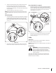
3. 4. Slide the wheel fully inward on the wheel shaft . Reinstall the wheel drive pin through the wheel shaft only (not through the wheel hub). See Fig. 3-5. The wheel should now spin freely (freewheel) on the wheel shaft. Repeat with the other wheel. Reverse Clutch Cable (If so equipped) 1. Use the handlebar to roll the tiller to a flat area. Carefully unwrap the reverse clutch cable (Red end fitting) from its shipping position.
4 Controls & Features Reverse Handle Assembly Forward Clutch Bail Depth Regulator Lever Handlebar Height Adjustment Tines Wheel Drive Pin NOTE: This Operator’s Manual covers several garden tiller models. The tiller depicted may differ from yours. Figure 4-1 Engine Controls For detailed information on all engine controls refer to the separate Engine Operator’s Manual. Wheel Drive Pins Each wheel is equipped with a wheel drive click pin that secures the wheel to the wheel shaft.
5 Operation WARNING! Before operating your machine, carefully read and understand this manual and all of its safety, operating and maintenance sections and instructions, along with all of the decals on the machine. Failure to follow these instructions can result in serious personal injury. 7. Fill the fuel tank with gasoline according to the directions in the separate Engine Operator’s Manual. Follow all instructions and safety rules carefully. 8.
Engage Drive & Tines Turning the Tiller 1. For forward motion of the wheels and power to the tines pull the Forward Clutch Bail up against the handlebar. Release the bail to stop the forward motion of the wheels and tines. Practice turning the tiller in a level, open area. Be very careful to keep your feet and legs away from the tines. 2. When tilling, relax and let the wheels pull the machine while the tines dig. Walk behind and a little to one side of the tiller.
• Avoid the temptation to push down on the handlebars in an attempt to force the tiller to dig deeper. Doing so takes the weight off the powered wheels, causing them to lose traction. Without the wheels to hold the tiller back, the tines will attempt to propel the tiller backward, towards the operator. • When cultivating (breaking up surface soil around plants to destroy weeds, see Fig. 5-4), Adjust the tines to dig only 1” to 2” deep.
Tilling on a Slope Loading & Unloading the tiller WARNING! Do not operate the tiller on a slope too steep for safe operation. Till slowly and be sure you have good footing. Never permit the tiller to freewheel down slopes. Failure to follow this warning could result in personal injury. 1. Till only on moderate slopes, never on steep ground where the footing is difficult. 2. Tilling up and down slopes is recommended rather than terracing.
6 Maintenance & Adjustments Maintenance Schedule Check After first 2 hours Before each use Every 5 Hours P P P Check Motor Oil Level Clean Engine Check Drive Belt Tension Check Nuts and Bolts Every 10 Hours Every 30 Hours P P P P P P Lubricate Tiller P P P Check Gear Oil Level in Transmission Check Tines for Wear Check Air Pressure in Tires WARNING! Before inspecting, cleaning or servicing the machine, shut off the engine, wait for all moving parts to come to a complete stop, disconnect the sp
Use a clean lubricating oil (#30 weight motor oil is suitable) and a clean general purpose grease (grease containing a metal lubricant is preferred, if available). • Remove the wheels, clean the wheel shaft and apply a thin coating of grease to the wheel shaft. • Grease the back, front and sides of the depth regulator lever. • Remove the tines and clean the tine shaft. Use a file or sandpaper to gently remove any rust, burrs or rough spots (especially around holes in the shaft).
7 Service Belt Replacement Removing/Installing a Tine Assembly: If the drive belt or reverse drive belt needs to be replaced, see your local authorized dealer or refer to the Replacement Parts Section for ordering information. Use only a factory-authorized belt as an “over- the-counter” belt may not perform satisfactorily. The procedure requires average mechanical ability and commonly available tools. 1. A tine assembly consists of eight tines mounted on a tine holder. 2.
4. Remove all dirt and clean the area around the transmission cover. See Fig. 7-3. Hex Screw Transmission Cover Transmission Housing Figure 7-3 18 5. Remove the four hex screws (5⁄16-18 x .75) securing the transmission cover to the drive shaft and remove the cover. See Fig. 7-3 6. Remove the left-side wheel. Tilt the left-side wheel shaft into a drain pan and allow the gear oil to drain through the top of the transmission. 7. Reinstall the wheel and reinstall the transmission cover. 8.
8 Troubleshooting Problem Wheels/Tines will not turn Tines turn, but wheels don’t Wheels turn, but tines Don’t Poor tilling performance Cause Remedy 1. Improper use of controls. 1. Review Operation section. 2. Worn, broken, or mis-adjusted drive belt(s). 2. Replace or adjust belts. 3. Internal transmission wear or damage. 3. Contact local authorized dealer. 4. Bolt loose in transmission pulley. 4. Tighten bolt. 1. Wheel Drive Pins not in WHEEL DRIVE. 1. Inserts Drive Pins properly. 2.
9 Replacement Parts Component Part Number and Description 954-04090 Forward Drive Belt 954-04091 Reverse Drive Belt (If so equipped) 946-04413 Forward Drive Cable 946-04414 Reverse Drive Cable (If so equipped) 742-04227 742-04226 Bolo Tine, 10” (LT) Bolo Tine, 10” (RT) 934-04232 Wheels, 13 x5 x 6 (65M & 655 model) 934-04453 Wheels, 11 x 4-4 (64M model) Phone (800) 828-5500 to order replacement parts or a complete Parts Manual (have your full model number and serial number ready).
Notes 10 21
Section 10— Notes
Section 10 — Notes 23
MANUFACTURER’S LIMITED WARRANTY FOR The limited warranty set forth below is given by Troy-Bilt LLC with respect to new merchandise purchased and used in the United States and/or its territories and possessions, and by MTD Products Limited with respect to new merchandise purchased and used in Canada and/ or its territories and possessions (either entity respectively, “TroyBilt”). b. Log splitter pumps, valves, and cylinders have a separate oneyear warranty.
Medidas importantes de seguridad • Configuración • Funcionamiento • Mantenimiento • Servicio • Solución de problemas • Garantía Manual del operador Bronco, Super Bronco & Pro-Line Cultivadora de dientes traseros ADVERTENCIA LEA Y RESPETE TODAS LAS NORMAS DE SEGURIDAD E INSTRUCCIONES INCLUIDAS EN ESTE MANUAL ANTES DE PONER EN FUNCIONAMIENTO ESTA MÁQUINA. SI NO RESPETA ESTAS INSTRUCCIONES PUEDE PROVOCAR LESIONES PERSONALES. TROY-BILT LLC, P.O.
1 Al propietario Gracias Gracias por comprar una Troy-Bilt cultivadora de jardín. La misma ha sido diseñada cuidadosamente para brindar excelente rendimiento si se la opera y mantiene correctamente. Por favor lea todo este manual antes de operar el equipo. Le indica cómo configurar, operar y mantener la máquina con seguridad y fácilmente.
2 Medidas importantes de seguridad ¡ADVERTENCIA! La presencia de este símbolo indica que se trata de instrucciones importantes de seguridad que se deben respetar para evitar poner en peligro su seguridad personal y/o material y la de otras personas. Lea y siga todas las instrucciones de este manual antes de poner en funcionamiento esta máquina. Si no respeta estas instrucciones puede provocar lesiones personales. Cuando vea este símbolo.
Manejo seguro de la gasolina: Para evitar lesiones personales o daños materiales tenga mucho cuidado cuando trabaje con gasolina. La gasolina es sumamente inflamable y sus vapores pueden causar explosiones. Si se derrama gasolina encima o sobre la ropa se puede lesionar gravemente ya que se puede incendiar. Lávese la piel y cámbiese de ropa de inmediato. a. Utilice sólo los recipientes para gasolina autorizados. b.
4. 5. 6. 7. 8. 9. 10. 11. Antes de limpiar, reparar o inspeccionar la máquina, detenga el motor y asegúrese de que los dientes y todas las partes móviles se hayan detenido. Desconecte el cable de la bujía y póngalo haciendo masa contra el motor para evitar que se encienda accidentalmente. No cambie la configuración del regulador del motor ni lo opere a sobrevelocidad. El regulador del motor controla la velocidad máxima de funcionamiento seguro del motor.
Símbolos de Seguridad Esta página describe los símbolos y figuras de seguridad internacionales que pueden aparecer en este producto. Lea el manual del operador para obtener la información terminada sobre seguridad, reunirse, operación y mantenimiento y reparación. Símbolo Descripción LEA EL MANUAL DEL OPERADOR (S) Lea, entienda, y siga todas las instrucciones en el manual (es) antes de intentar reunirse y funcionar. LA ADVERTENCIA — LOS DIENTES ROTATIVO No ponga manos o pies cerca del giro de partes.
3 Montaje y Configuración Contenido de la caja de cartón • Una cultivadora • Un botella de 20 onzas de aceite SAE 10W30 • Un Manual del operador • Un Manual del operador del motor NOTA: Este manual de operación cubre distintos modelos de cultivadora de jardín. La cultivadora que se exhibe aquí puede diferir de la suya.
2. Utilizando los dos tornillos hexagonales y las dos tuercas de seguridad con brida, acople sin apretar el soporte del manillar utilizando los orificios superiores. Apriete los dos tornillos con firmeza. Vea la Fig. 3-2. 4. Hay tres orificios de ajuste de la altura en las dos ménsulas de soporte del manillar. Use un ajuste que posicione los manillares aproximadamente al nivel de la cintura cuando los dientes se encuentran a 3”-4” dentro del suelo.
2. Retire el pasador de transmisión de la rueda del cubo de la rueda y eje de la rueda. Vea la Fig. 3-5. 3. Deslice la rueda totalmente hacia adentro en el eje de la rueda. Reinstale el pasador de transmisión en las ruedas a través del eje de la rueda únicamente (no a través del cubo de la rueda). Ver Fig. 3-5. Ahora, la rueda debe girar libremente (ruedas libres) sobre el eje de la rueda. Repita el procedimiento con la otra rueda. 4. Use el manillar para hacer rodar la cultivadora hasta un área plana.
4 Controles y Características Montaje del mango de marcha atrás Gancho de embrague de marcha directa Palanca del regulador de profundidad Ajuste de la altura del manillar Dientes Pasador de transmisión en las ruedas Figura 4-1 NOTA: Este manual de operación cubre distintos modelos de Montaje del mango de marcha atrás (Si lo tiene) cultivadora de jardín. La cultivadora que se exhibe aquí puede El gancho del embrague de marcha atrás controla el engranado diferir de la suya.
5 Funcionamiento ¡ADVERTENCIA! Antes de hacer funcionar la máquina, lea con atención este manual y todas las instrucciones de las secciones de seguridad, funcionamiento y mantenimiento, además de todas las calcomanías que se encuentran en la máquina. Si no se observan estas instrucciones se pueden producir lesiones personales graves. Introducción 7. Llene el tanque de gasolina de acuerdo con las instrucciones del Manual del operador del motor que se entrega por separado.
Detención del motor b. En los modelos sin mango inversa: • Consulte el Manual del Operador del Motor para más instrucciones sobre cómo detener el motor. Liberar la fianza de embrague de marcha adelante. A continuación, levante el manillar hasta que los dientes no toquen el suelo. • Para el movimiento de las ruedas hacia adelante y la potencia en los dientes Jale el gancho del embrague de marcha directa hacia arriba contra la barra de control.
• Si se produce enmarañado, levante los dientes del suelo y pase la cultivadora marcha atrás durante unos cuantos pies. Esta acción de marcha atrás debe desprender una buena cantidad de desechos. Modelos de labranza sugeridos • ¡ADVERTENCIA! Antes de despejar los dientes a mano, detenga el motor, deje que todas las partes en movimiento se detengan y desconecte el cable de la bujía. Si no se observa esta advertencia se pueden producir lesiones personales.
• Si las dimensiones del jardín no permiten la labranza en sentido longitudinal y luego en sentido transversal, traslape las primeras pasadas por la mitad del ancho de la cultivadora, continuando con sucesivas pasadas a un cuarto del ancho. Vea la Fig. 5-7. que levante los manillares levemente al ir cuesta arriba. Al realizar la labranza cuesta abajo, traslape la primera pasada en aproximadamente la mitad del ancho de la cultivadora. Jardinería en terrazas 1.
Carga y descarga de la cultivadora ¡ADVERTENCIA! La carga y descarga de la cultivadora en un vehículo es potencialmente peligrosa y no se recomienda a menos que sea absolutamente necesario, ya que esto podría resultar en lesiones personales o daños materiales. Sin embargo, si debe cargar o descargar la cultivadora, siga las pautas que se suministran a continuación.
6 Mantenimiento y Ajustes Programa de mantenimiento Verifique después de las primeras 2 horas Antes de cada uso Cada 10 horas Cada 30 horas P P Verifique el nivel de aceite Limpie el motor Verifique las tuercas y los pernos Cada 5 horas P P P P P Lubrique la cultivadora P Realice el mantenimiento del filtro de aire del motor P P Verifique el desgaste de los dientes Verifique la presión de aire de los neumáticos ¡ADVERTENCIA! Antes de inspeccionar, limpiar o realizar el mantenimiento de la má
Use aceite lubricante limpio (es adecuado el aceite para motores de peso #30) y grasa de uso general limpia (es preferible grasa que contenga un lubricante de metal, si lo hay). 6. Si el nivel de aceite del engranaje está bajo, agregue aceite como se describe a continuación. Si el nivel de aceite del engranaje es correcto, vuelva a colocar el tapón de llenado de aceite. • Retire las ruedas, limpie el eje de las ruedas y aplíquele una capa delgada de grasa. 7.
7 Servicio Cambio de correa Retiro/Instalación de un solo diente Si es necesario cambiar la correa de transmisión de marcha atrás, vea al distribuidor local autorizado o consulte la sección de piezas de reemplazo para obtener la información y realizar el pedido. Use únicamente correas autorizadas por el fabricante, ya que las correas genéricas pueden no desempeñarse satisfactoriamente. El procedimiento requiere habilidad mecánica media y herramientas habitualmente disponibles. 1.
Cambio de aceite del engranaje de la transmisión NOTA: El aceite del engranaje de la transmisión no necesita ser cambiado a menos que se contamine con suciedad, arena o partículas de metal. 1. Vacíe la gasolina del tanque o haga funcionar el motor hasta que el tanque de combustible esté vacío. 2. Drene el aceite del motor. 3. Retire el tornillo de la arandela hexagonal (1⁄4-20 x .500) y la arandela plana (.28 x .74 x .
8 Solución de Problemas Problema Las ruedas y los dientes no giran Los dientes giran, las ruedas no. Las ruedas giran, los dientes no. Rendimiento deficiente de la labranza 20 Causa Solución 1. Uso incorrecto de los controles. 1. Revise la sección de Funcionamiento 2. Correa(s) de transmisión desgastada(s), rota(s) o mal ajustada(s). 2. Reemplace o ajuste las correas. 3. Trasmisión interna desgastada o dañada. 3. Contacte con su distribuidor local autorizado. 4.
Notas 9 21
22 Sección 9— Notas
Sección 9 — Notas 23
GARANTÍA LIMITADA DEL FABRICANTE PARA La siguiente garantía limitada es otorgada por Troy-Bilt LLC con respecto a nuevos productos adquiridos y utilizados en Estados Unidos y/o sus territorios y posesiones, y por MTD Products Limited con respecto a nuevos productos adquiridos y utilizados en Canadá y/o sus territorios y posesiones (cualquiera de las dos entidades, respectivamente, “Troy-Bilt”).