For Parts Call 606-678-9623 or 606-561-4983 Professional Shop Manual 78/83/90 Series Horizontal Shaft Engines (277/357/420 cc Engines) NOTE: These materials are for use by trained technicians who are experienced in the service and repair of outdoor power equipment of the kind described in this publication, and are not intended for use by untrained or inexperienced individuals. These materials are intended to provide supplemental information to assist the trained technician.
For Parts Call 606-678-9623 or 606-561-4983 www.mymowerparts.
For Parts Call 606-678-9623 or 606-561-4983 Table of Contents Chapter 1: Introduction Professional Service Manual Intent . . . . . . . . . . . . . . . . . . . . . . . . . . . . . . . . 1 Safety . . . . . . . . . . . . . . . . . . . . . . . . . . . . . . . . . . . . . . . . . . . . . . . . . . . . . . 1 Fasteners. . . . . . . . . . . . . . . . . . . . . . . . . . . . . . . . . . . . . . . . . . . . . . . . . . . . 3 Assembly instructions . . . . . . . . . . . . . . . . . . . . . . . . . . . . . . . . . . .
For Parts Call 606-678-9623 or 606-561-4983 Chapter 4: The Fuel System and Governor Inspecting the fuel . . . . . . . . . . . . . . . . . . . . . . . . . . . . . . . . . . . . . . . . . . . . 37 Test fuel for alcohol . . . . . . . . . . . . . . . . . . . . . . . . . . . . . . . . . . . . . . . . . . . 38 Fuel tank vent . . . . . . . . . . . . . . . . . . . . . . . . . . . . . . . . . . . . . . . . . . . . . . . . 39 The fuel filter . . . . . . . . . . . . . . . . . . . . . . . . . . . . . . . . . . . . . .
For Parts Call 606-678-9623 or 606-561-4983 Chapter 7: Ignition System Troubleshooting the ignition system . . . . . . . . . . . . . . . . . . . . . . . . . . . . . . . 81 Stop switch . . . . . . . . . . . . . . . . . . . . . . . . . . . . . . . . . . . . . . . . . . . . . . . . . . 82 Remote (ignition) stop switch (snow engines) . . . . . . . . . . . . . . . . . . . . . . . 83 Test for ignition that won’t turn off . . . . . . . . . . . . . . . . . . . . . . . . . . . . . . . . 84 The module . . . . . . .
For Parts Call 606-678-9623 or 606-561-4983 IV www.mymowerparts.
For Parts Call 606-678-9623 or 606-561-4983 Introduction CHAPTER 1: INTRODUCTION Professional Service Manual Intent This manual is intended to provide service dealers with an introduction to proven diagnostic and repair procedures for 78/83/90 series MTD horizontal shaft engines. Disclaimer: The information contained in this manual is correct at the time of writing. Both the product and the information about the product are subject to change without notice.
For Parts Call 606-678-9623 or 606-561-4983 78/83/90 Series Horizontal Shaft Engines • Be prepared in case of emergency: ! CAUTION Keep a fire extinguisher nearby Keep a first aid kit nearby Keep emergency contact numbers handy • Replace any missing or damaged safety labels on shop equipment. • Replace any missing or damaged safety labels on equipment being serviced. • Grooming and attire: ! WARNING Do not wear loose fitting clothing that may become entangled in equipment.
For Parts Call 606-678-9623 or 606-561-4983 Introduction Fasteners • Most of the fasteners used on the MTD engine are metric. Some are fractional inches. For this reason, wrench sizes are frequently identified in the text, and measurements are given in U.S. and metric scales. • If a fastener has a locking feature that has worn, replace the fastener or apply a small amount of releasable thread locking compound such as Loctite® 242 (blue).
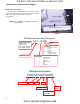
For Parts Call 606-678-9623 or 606-561-4983 78/83/90 Series Horizontal Shaft Engines Model and serial number The model and serial number can be found on a white sticker with a bar code. The sticker is located on the right side of the engine at the bottom of the block. See Figure 1.1. Front of engine NOTE: The serial number will always start with the model number. Model /serial number Figure 1.1 MTD Horizontal Engine Model Designators Starter/Alternators 161- SHA 1=Recoil start 2=Electric start 3=E.
For Parts Call 606-678-9623 or 606-561-4983 Introduction Maintenance The information in this manual applies to the MTD engine. Some basic principles may apply to engines produced by other manufacturers. As the saying goes “an ounce of prevention is worth a pound of cure”. The same can be said about preventive maintenance on outdoor power equipment. By changing the spark plug and oil at recommended intervals many failures can be avoided.
For Parts Call 606-678-9623 or 606-561-4983 78/83/90 Series Horizontal Shaft Engines Air filter (summer engines) Generally air filters come in two different types, a pleated-paper element or foam. A combination of the two are used on the MTD engine. See Figure 1.3. 1. Paper-pleated element The main function of the air filter is to trap air borne particles before they enter the engine. Dirt ingestion can cause serious internal engine damage.
For Parts Call 606-678-9623 or 606-561-4983 Introduction Oil type and capacity MTD engines use oil with a SF/SG API rating or better is the recommended oil for this engine. The winter engines use SAE 5W-30 oil and the summer engines use SAE 10W-30 oil. The oil capacity for all of the 78/83/90 series engines is 37 fl.oz (1.1 liters). • Check the oil level frequently and change the oil more frequently in severe operating conditions such as exceptionally deep snow falls.
For Parts Call 606-678-9623 or 606-561-4983 78/83/90 Series Horizontal Shaft Engines To check the oil with a threaded dip stick: 1. Twist and remove the dip stick from the engine. 2. Clean the oil off of the tip of the dipstick. 3. Re-insert the dipstick without threading it in to get the oil level reading. See Figure 1.5. 4. The oil level is determined by the lowest point on the dipstick that is completely covered with oil. Do not thread dipstick in to check the oil level Figure 1.
For Parts Call 606-678-9623 or 606-561-4983 Introduction Fuel Gasolines currently on the market are not pure gasoline. Today’s fuels have alcohol and other additives in them to reduce emissions. The fuel make up can vary seasonally and geographically. Fuel with alcohol added to it is sometimes referred to as “oxygenated fuel”. The extra oxygen carried by the ethanol increases the oxidation of the fuel. This speeds up the process that causes the fuel to go bad.
For Parts Call 606-678-9623 or 606-561-4983 78/83/90 Series Horizontal Shaft Engines To replace the fuel filter: Front fuel tank shroud To avoid personal injury or property damage, use extreme care in handling gasoline. Gasoline is extremely flammable and the vapors are explosive. Serious personal injury can occur when gasoline is spilled on yourself and/or your clothes which can ignite. Wash your skin and change clothes immediately. ! W A R N IN G 1. Siphon the fuel out of the fuel tank. 2.
For Parts Call 606-678-9623 or 606-561-4983 Introduction Valve lash Valve lash is the clearance between the top of the valve stem and the rocker arm. The valve lash should be checked after the first 25 hours of use and every 100 hours after that. Valve lash can be checked and adjusted using the following steps: Spark plug socket 1. If the engine has been run, allow it to cool thoroughly. Position the equipment for easy access to the cylinder head. 2.
For Parts Call 606-678-9623 or 606-561-4983 78/83/90 Series Horizontal Shaft Engines 6. Slowly pull the starter rope until air can be heard coming out of the spark plug hole. 7. Confirm that the piston is at Top-Dead-Center on the compression stroke. See Figure 1.13. • • The compression stroke can be distinguished from the overlap stroke by the presence of air pressure at the spark plug hole and the fact that neither of the valves should move significantly on the compression stroke.
For Parts Call 606-678-9623 or 606-561-4983 Introduction 13. Double-check the clearance after tightening the jam nut, to confirm that it did not shift. Re-adjust if necessary. 14. Rotate the engine through several compression cycles: • Observe the movement of the valve gear. • Return the piston to TDC compression stroke and re-check the valve lash to confirm consistent movement of the valve gear, including the slight bump to the exhaust valve from the automatic compression release. 15.
For Parts Call 606-678-9623 or 606-561-4983 78/83/90 Series Horizontal Shaft Engines General torque specifications VL]H 0 0 0 0 LQ OEV 1P LQ OEV 1P LQ OEV 1P LQ OEV 1P LQ OEV 1P *UDGH 1RQFULWLFDO )DVWHQHUV LQ $OXPLQXP VL]H 0 0 0 IW OEV 1P IW OEV 1P IW OEV 1P
For Parts Call 606-678-9623 or 606-561-4983 Introduction Frequently used specifications Minimum in. mm Maximum in. mm Intake valve lash 78 0.004 0.10 0.006 0.15 83 0.004 0.10 0.006 0.15 90 0.004 0.10 0.006 0.15 78 0.006 0.15 0.008 0.20 83 0.006 0.15 0.008 0.20 90 0.006 0.15 0.008 0.20 78 0.026 0.65 0.030 0.75 83 0.026 0.65 0.030 0.75 90 0.026 0.65 0.030 0.75 78 0.016 0.40 0.024 0.60 83 0.016 0.40 0.024 0.60 90 0.016 0.40 0.024 0.
For Parts Call 606-678-9623 or 606-561-4983 78/83/90 Series Horizontal Shaft Engines 16 www.mymowerparts.
For Parts Call 606-678-9623 or 606-561-4983 BASIC TROUBLESHOOTING CHAPTER 2: BASIC TROUBLESHOOTING Definitions Troubleshooting - The act of gathering information by preforming tests and direct observations. Diagnosis - Developing and testing theories of what the problem is, based on the information gathered in troubleshooting. Introduction Diagnosing an engine is an art form that is built upon several factors. First and most importantly is a good understanding of how the engine works.
For Parts Call 606-678-9623 or 606-561-4983 78/83/90 Series Horizontal Shaft Engines IV. Unusual exhaust tone There are tools that the technician can use in order to define the problem, such as: 1. Interview the customer. 1a. Get a good description of their complaint. 1b. If it is an intermittent problem, verify what conditions aggravate the problem as best as possible. 1c. Get an accurate service history of the equipment. 1d. Find out how the customer uses and stores the equipment. 2.
For Parts Call 606-678-9623 or 606-561-4983 BASIC TROUBLESHOOTING D. Rope jerks back. This usually indicates that the piston is stopping before top dead center on the compression stroke and is being driven back down by compression or combustion. The likely suspects are: I. Compression that is unusually high. a. valve lash. b. a partial hydraulic lock. III. Ignition timing is advanced. a. Improper air gap. b. Sheared or missing flywheel key. c. The wrong flywheel or module is installed on the engine. IV.
For Parts Call 606-678-9623 or 606-561-4983 78/83/90 Series Horizontal Shaft Engines VI. Check valve timing/actuation. VII. Check exhaust. 3. Starts, runs poorly 3a. Starts, then dies I. Run the engine with a spark tester in-line between the spark plug wire and the spark plug or use an oscilloscope and see if the spark goes away at the same time the engine dies. II. Check choke operation. a. Black smoke? b. Wet plug? III. Prime test immediately after engine dies.
For Parts Call 606-678-9623 or 606-561-4983 BASIC TROUBLESHOOTING b. Intake blockage • An intake blockage up-stream of the carburetor will cause a rich fuel/air mixture and constrict the amount of air that the engine can draw in, limiting performance. • The intake valve not fully opening. A possible cause of this is loose valve lash. V. Makes unusual smoke when running a. Black smoke, usually heavy, usually indicates a rich air fuel mixture • Not enough air: air flow blockage or a partially closed choke.
For Parts Call 606-678-9623 or 606-561-4983 78/83/90 Series Horizontal Shaft Engines • Low octane fuel • Over-heating engine (check for blocked cooling air flow) • Carbon build-up in cylinder: glowing carbon chunks pre-igniting air fuel mix. d. Chirp • Compression, blowing-by the fire-ring of a damaged head gasket will sometimes produce a chirping noise. • Confirm with a compression test and leak-down test. e. Unusual exhaust tone Splashy or blatty • Splashy idle usually indicates a slight rich condition.
For Parts Call 606-678-9623 or 606-561-4983 BASIC TROUBLESHOOTING Repairing the problem The third step in the troubleshooting process is to repair the problem. This step consists of: A. Form a diagnosis by using all of the information gathered from the troubleshooting that was performed. B. Physically perform the repair. The fourth, and hopefully final, step in the troubleshooting process is the follow through. This step consists of: A.
For Parts Call 606-678-9623 or 606-561-4983 78/83/90 Series Horizontal Shaft Engines Prime test To perform a prime test: 1. Prime the engine through the carburetor throat using a squirt bottle, filled with clean fresh gasoline. 2. Make sure the throttle is in the run position and the safety key if fully inserted. 3. Attempt to start the engine. 4. If the engine starts and runs long enough to burn the prime, the problem is effectively isolated to the fuel system.
For Parts Call 606-678-9623 or 606-561-4983 BASIC TROUBLESHOOTING 7. Compare the results to the following chart. Leak-down Testing Results Symptom Possible cause Air escaping from the breather Worn cylinder or piston rings.
For Parts Call 606-678-9623 or 606-561-4983 78/83/90 Series Horizontal Shaft Engines Compression test To perform a compression test: NOTE: Compression should be in the range of 40-75 PSI (2.8-5.2 Bar). • Disconnect the high-tension lead from the spark plug and ground it well away from the spark plug hole. • Remove the spark plug using a 13/16” or 21mm wrench. A flexible coupling or “wobbly” extension may help. • Pull the starter rope several times to purge any fuel or oil from the combustion chamber.
For Parts Call 606-678-9623 or 606-561-4983 BASIC TROUBLESHOOTING PCV testing The PCV (Positive Crankcase Ventilation) valve is located in the valve cover and allows the crankcase pressure to escape. Leakage and blockage are the two failure modes for a PCV system. Either mode will cause crankcase pressure to build-up, though the effects of a blocked PCV are generally more dramatic. Increased case pressure will result in oil entering the combustion chamber. crankcase air chamber Figure 2.3 1.
For Parts Call 606-678-9623 or 606-561-4983 78/83/90 Series Horizontal Shaft Engines 28 www.mymowerparts.
For Parts Call 606-678-9623 or 606-561-4983 AIR INTAKE SYSTEMS CHAPTER 3: AIR INTAKE SYSTEMS MTD builds horizontal crank engines for snow blowers and chore performers. The differences between snow engines and chore engines are the muffler and the air intake system. Therefore the air intake system for the snow and chore engines will be discussed separately, as will the mufflers in a later chapter.
For Parts Call 606-678-9623 or 606-561-4983 78/83/90 Series Horizontal Shaft Engines Air filter (summer engines) Generally air filters come in two different types, a pleated-paper element or foam. A combination of the two are used on the MTD engine. • Air filters used on the MTD engine are designed to prevent particles larger than 3-5 micron from passing through into the engine. • The filter should be checked on a regular basis possibly several times in a season.
For Parts Call 606-678-9623 or 606-561-4983 AIR INTAKE SYSTEMS 5. Install the air filter by following the previous steps in reverse order. NOTE: When installing the air filter, the hole in the bottom of the paper element must fit over the riser in the air filter base. See Figure 3.6. Riser Air filter base Figure 3.6 31 www.mymowerparts.
For Parts Call 606-678-9623 or 606-561-4983 78/83/90 Series Horizontal Shaft Engines Air filter base and control panel (summer engines) To remove/replace the air filter base and control panel: 1. Remove the air filter following the steps described in the previous section. 2. Remove the three screws that hold the air filter base to the intake elbow. See Figure 3.7. Air filter base Screws Figure 3.7 3. Pull off the throttle lever knob. See Figure 3.8. 4.
For Parts Call 606-678-9623 or 606-561-4983 AIR INTAKE SYSTEMS Breather hose NOTE: All summer engines built on or after January 1, 2011 will have a hose from the evaporative emissions (EVAP) system attached to the control panel above the breather hose. See Figure 3.10. 9. Pull the control panel straight off the front of the engine. 10. Install the control panel by following the previous steps in reverse order. EVAP hose NOTE: tighten the carburetor nuts to a torque of 80 - 106 in lbs (9 - 12 Nm). 11.
For Parts Call 606-678-9623 or 606-561-4983 78/83/90 Series Horizontal Shaft Engines Carburetor and Insulator 1. Siphon the fuel out of the fuel tank. Remove these screws To avoid personal injury or prop! WARNING erty damage, use extreme care in handling gasoline. Gasoline is extremely flammable and the vapors are explosive. Keep away from sources of ignition. Serious personal injury can occur when gasoline is spilled on yourself and/or your clothes which can ignite.
For Parts Call 606-678-9623 or 606-561-4983 AIR INTAKE SYSTEMS Throttle linkage 4. Remove the Heat box (snow engines) or the control panel (summer engines) by following the steps described in appropriate section of this chapter. 5. Disconnect the throttle linkage and spring. See Figure 3.13. 6. Slide the carburetor off of the mounting studs. 7. Remove the carburetor. NOTE: The barb on the carburetor inlet is very sharp.
For Parts Call 606-678-9623 or 606-561-4983 78/83/90 Series Horizontal Shaft Engines NOTE: An insulator block separates the carburetor from the cylinder head. There is a gasket on each side of the insulator. See Figure 3.16. NOTE: The gaskets are different, and there is an orientation to the insulator. 9. • The bowl vent channel in the insulator faces the carburetor, with the exit toward the bottom. • There is a small hole in the insulator to carburetor gasket.
For Parts Call 606-678-9623 or 606-561-4983 FUEL SYSTEM AND GOVERNOR CHAPTER 4: THE FUEL SYSTEM AND GOVERNOR The function of the fuel system is to store fuel, mix the fuel with air in the correct ratio and deliver it to the intake port. The fuel system consists of the following components: • Fuel tank • Fuel lines • Fuel filter • Carburetor NOTE: When working on the fuel systems, look at the whole system. A problem will rarely be isolated to one component.
For Parts Call 606-678-9623 or 606-561-4983 78/83/90 Series Horizontal Shaft Engines Test fuel for alcohol Fuels currently on the market contain a wide array of additives. Some of these additives oxygenate the fuel. Oxygenated fuel reduces emissions, and is required in some parts of the United States. Fuel make-up varies seasonally and geographically. Ethanol is the primary additive used to oxygenate fuel. Ethanol in fuel creates a lot of problems for gasoline engines.
For Parts Call 606-678-9623 or 606-561-4983 FUEL SYSTEM AND GOVERNOR Fuel tank vent The fuel tank vent performs the important task of allowing air into the fuel tank. As fuel is being used by the engine, the fuel level in the tank drops. The dropping fuel level then creates a vacuum in the tank. If the fuel tank could not draw air through the vent, the vacuum would prevent the fuel from getting to the carburetor. The vent is located in the fuel cap. See Figure 4.3. Fuel cap Vent Figure 4.
For Parts Call 606-678-9623 or 606-561-4983 78/83/90 Series Horizontal Shaft Engines The fuel filter The fuel filter is located in the fuel tank nipple. It can be removed and cleaned with a can of carb cleaner or it can be replaced. See Figure 4.4. NOTE: If cleaning a filter, back-flush it by spraying the carb cleaner through the barb end and out of the screen. Also make sure the fuel tank is clean. Inset: Fuel filter/barb Filter Figure 4.
For Parts Call 606-678-9623 or 606-561-4983 FUEL SYSTEM AND GOVERNOR The fuel tank To remove the fuel tank: 1. Drain the tank. 2. Remove the four screws that secure the fuel tank using a 12 mm wrench. See Figure 4.5. 3. Lift up on the fuel tank and disconnect the fuel line. See Figure 4.6. Remove these screws Figure 4.5 Disconnect the fuel line Figure 4.6 NOTE: On engines equipped with an EVAP system, disconnect the hose from the roll over valve. See Figure 4.7. Roll over valve 4.
For Parts Call 606-678-9623 or 606-561-4983 78/83/90 Series Horizontal Shaft Engines Evaporative (EVAP) emissions system Gasoline is made from the graduated distillation of crude oil. It consists of a multitude of individual hydrocarbons and has a boiling range of 86 - 410°F (30-210°C)1. The large quantity of hydrocarbons and the low boiling range makes gasoline an ideal fuel for spark ignited, internal combustion engines. However, the hydrocarbons are not good for the environment.
For Parts Call 606-678-9623 or 606-561-4983 FUEL SYSTEM AND GOVERNOR This system operates as follows: Unvented 1. The gasoline evaporate and lets off vapors. 2. The vapors exit the fuel tank through the roll over valve vent. NOTE: The fuel cap used with the charcoal canister system is not vented. If a vented cap is used, the EVAP system will not work. See Figure 4.9. NOTE: The new EPA standard also requires the fuel caps to be tethered to the fuel tank. Tethered Figure 4.9 3.
For Parts Call 606-678-9623 or 606-561-4983 78/83/90 Series Horizontal Shaft Engines Troubleshooting the EVAP System There are four failure modes for the EVAP system: • A leak in the system - will allow dirt ingestion. • A blockage in the system (between the canister and the fuel tank) - acts a plugged vent. • A blockage in the system (between the canister and the control panel) - The canister can not purge its vapors.
For Parts Call 606-678-9623 or 606-561-4983 FUEL SYSTEM AND GOVERNOR Testing the roll over valve The roll over valve vent has two functions. The first function is to vent the tank and the second function is to close off the vent if the tank is inverted. Hose to roll over valve Test the roll over valve by: 1. Disconnect the hose that runs from the charcoal canister to the roll over valve. See Figure 4.14. 2. Connect a vacuum pump to the hose. 3. Slowly apply a vacuum to the roll over valve.
For Parts Call 606-678-9623 or 606-561-4983 78/83/90 Series Horizontal Shaft Engines Charcoal canister To remove/replace the charcoal canister: 1. Disconnect the hoses from the canister. See Figure 4.15. Hoses Figure 4.15 2. Remove the screw from the canister mounting strap using a 10 mm wrench. See Figure 4.16. Screw Figure 4.16 To Install the canister: 3. Insert the tab of the mounting strap into the slot in the fuel tank mounting bracket. See Figure 4.17. 4. Install the mounting screw. 5.
For Parts Call 606-678-9623 or 606-561-4983 FUEL SYSTEM AND GOVERNOR Roll over valve To remove the roll over valve: 1. Grommet Gently pry the grommet from in between the roll over valve and the fuel tank. See Figure 4.18. NOTE: Leaving the hose connected to the roll over valve will help prevent it from falling inside the tank once the grommet is removed. 2. Lift the valve out of the fuel tank. 3. Disconnect the hose. Figure 4.18 To install the roll over valve: Roll over valve assembly 1.
For Parts Call 606-678-9623 or 606-561-4983 78/83/90 Series Horizontal Shaft Engines Choke 78/83/90 series MTD engines are equipped with a choke. The snow engines are also equipped with a primer, both of which must be used to start the engine. NOTE: The choke should be opened after the engine starts. This can be a source of starting issues with customers who are not familiar with manual chokes. NOTE: On the summer engines, the entire choke mechanism is part of the carburetor. See Figure 4.20.
For Parts Call 606-678-9623 or 606-561-4983 FUEL SYSTEM AND GOVERNOR The choke rod is part of the heat box assembly mounted on the front of the carburetor. See Figure 4.22. Choke rod Heat box Figure 4.22 NOTE: The choke rod can be bent slightly to facilitate adjustment. To adjust the choke rod: Choke rod 1. Remove the choke knob and the engine shroud by following the steps described in Chapter 3: Air Intake Systems. 2. Rotate the choke knob shaft to verify full choke movement. See Figure 4.23. 3.
For Parts Call 606-678-9623 or 606-561-4983 78/83/90 Series Horizontal Shaft Engines Primers (snow engines) MTD engines use a dry bulb primer. This means that there is no fuel in the primer bulb. The primer works by pushing air into the float chamber of the carburetor when the primer bulb is depressed. This will force fuel to be sprayed out of the main nozzle into the throat of the carburetor. To test the primer: 1.
For Parts Call 606-678-9623 or 606-561-4983 FUEL SYSTEM AND GOVERNOR Carburetors If diagnosis indicates a fuel problem, inspect the carburetor. This is important even if problems are identified elsewhere in the fuel system. IMPORTANT: the fuel must be tested for alcohol content before diagnosing anything else on the engine. NOTE: It is important to perform a compression or leak down test before condemning a carburetor.
For Parts Call 606-678-9623 or 606-561-4983 78/83/90 Series Horizontal Shaft Engines Disassembly and rebuilding of the carburetor 1. Clamp-off the fuel line to prevent fuel spillage, then disconnect the fuel line from the carburetor. 2. Disconnect the primer hose. 3. Remove the carburetor by following the steps described in Chapter 3: Air Intake and Filter. NOTE: An insulator separates the carburetor from the cylinder head.
For Parts Call 606-678-9623 or 606-561-4983 FUEL SYSTEM AND GOVERNOR Float bowl 8. Drain bolt Remove the pin that the float hinges on to remove the float. NOTE: The float is not adjustable. Spring tension against the float valve begins to build from the horizontal position, putting progressively more pressure between the tip of the valve and the seat. See Figure 4.28. Flat fiber gasket Bowl bolt with recess in head for O-ring Gasket seal Figure 4.
For Parts Call 606-678-9623 or 606-561-4983 78/83/90 Series Horizontal Shaft Engines Emulsion air port: pilot jet NOTE: The main jet secures the emulsion tube in the central column of the carburetor. See Figure 4.30. Emulsion tube Main jet Emulsion air port: main jet Figure 4.30 10. The throttle stop screw has a large pliable lip around the head of the screw. That lip secures a metering plug for the pilot and transition ports. Remove the screw to reach the plug. See Figure 4.31.
For Parts Call 606-678-9623 or 606-561-4983 FUEL SYSTEM AND GOVERNOR End view 12. Examine the metering plug: See Figure 4.33. • Fuel, drawn from the central column via the long fuel feed leg, is metered by the brass orifice in the tip of the metering plug. O-rings • Air, drawn from the emulsion air port, is metered by the size of the brass orifice at the entrance to the port. Air passage Fuel metering orifice • The metering plug creates a small venturi.
For Parts Call 606-678-9623 or 606-561-4983 78/83/90 Series Horizontal Shaft Engines Fuel shut-off valve To prevent the needle valve from un-seating and flooding the engine while being towed, engines designed to go onto log splitters have a fuel shut-off valve built into the carburetor. To service the shut-off valve: 1. Remove the carburetor by following the procedures described in Chapter 3: Air Intake Systems. 2. Remove the choke lever pivot screw. See Figure 4.36. 3.
For Parts Call 606-678-9623 or 606-561-4983 FUEL SYSTEM AND GOVERNOR 6.Remove the fuel shut-off lever. See Figure 4.38. Fuel shut-off lever Figure 4.38 Fuel passage NOTE: There is a passage cast into the shut-off lever. When this passage lines up with the two posts in the carburetor, fuel will flow to the needle valve. Figure 4.39 7. Remove the rubber gasket. See Figure 4.40. 8. Re-assemble the fuel shut-off valve by following the previous steps in reverse order. 9.
For Parts Call 606-678-9623 or 606-561-4983 78/83/90 Series Horizontal Shaft Engines Governor The engine speed is controlled by a balance between the force applied by a spring (pulling the throttle open) and a flyweight mechanism within the engine applying force to the governor arm (pushing the throttle closed). See Figure 4.41. Spring tension NOTE: While the mechanism is simple and robust, it is important to pay attention when working on parts near the governor.
For Parts Call 606-678-9623 or 606-561-4983 FUEL SYSTEM AND GOVERNOR Governor shaft To remove or replace the governor shaft: Remove hairpin clip 1. Remove the engine from the equipment that it powers. 2. Remove the governor arm by following the previously described steps. 3. Remove the flywheel by following the steps described in Chapter 7: Ignition Systems. 4. Remove the crank case cover and crankshaft from the engine by following the steps described in Chapter 10: Cam, Crankshaft and Piston. 5.
For Parts Call 606-678-9623 or 606-561-4983 78/83/90 Series Horizontal Shaft Engines Governor cup and the governor gear The Governor gear and cup are located inside the crankcase cover. The flyweights and the governor cup are inter locked on this family of engines. The governor gear and cup are serviced as a complete assembly. 1. Remove the engine from the equipment that it powers. 2. Remove the crank case cover from the engine by following the steps described in Chapter 10: Cam, Crankshaft and Piston.
For Parts Call 606-678-9623 or 606-561-4983 FUEL SYSTEM AND GOVERNOR Governor adjustment To adjust the governor: Loosen nut 1. Remove the fuel tank by following the procedures described in the fuel tank section of this chapter. 2. Loosen the governor arm nut but do not remove the nut completely. 3. Pry open the governor arm crimp with a flat head screwdriver. See Figure 4.47. 4.
For Parts Call 606-678-9623 or 606-561-4983 78/83/90 Series Horizontal Shaft Engines 62 www.mymowerparts.
For Parts Call 606-678-9623 or 606-561-4983 Lubrication CHAPTER 5: LUBRICATION Oil type and quantity MTD engines use oil with a SF/SG API rating or better is the recommended oil for this engine. • The winter engines use SAE 5W-30 oil. • The summer engines use SAE 10W-30 oil. • The oil capacity for all of the 78/83/90 series engines is 37 fl.oz (1.1 liters).
For Parts Call 606-678-9623 or 606-561-4983 78/83/90 Series Horizontal Shaft Engines Oil dip stick NOTE: There are two types of dip sticks that can be found on MTD engines; a threaded dip stick that was used on older engines and a quarter turn dip stick that is used on engines currently being produced. See Figure 5.1. Threaded 1/4 turn Figure 5.1 To check the oil with a threaded dip stick: 1. Twist and remove the dip stick from the engine. 2. Clean the oil off of the tip of the dipstick. 3.
For Parts Call 606-678-9623 or 606-561-4983 Lubrication Dip stick tube removal To remove/replace the dip stick tube: NOTE: The procedure to remove the dip stick tube is the same for both styles of dip stick. Remove these screws NOTE: A threaded dip stick and tube assembly is interchangeable with a quarter turn dip stick and tube assembly. 1. Remove the upper screw that secures the dip stick tube to the fuel tank support bracket using a 10 mm wrench. See Figure 5.4. 2.
For Parts Call 606-678-9623 or 606-561-4983 78/83/90 Series Horizontal Shaft Engines Lubrication system MTD uses a splash lube system for its horizontal shaft engines. The connecting rod has a dipper on it that “splashes” oil around the inside of the engine. See Figure 5.5. NOTE: The cam and the balance shaft were removed for a better view of the lubrication system. Dipper Figure 5.5 The splashing action will create an oil mist that reaches the cylinder head.
For Parts Call 606-678-9623 or 606-561-4983 Lubrication Positive crankcase ventilation valve Breather hose To remove the valve cover and PCV valve: NOTE: The PCV valve is located inside the valve cover. The function and test procedures for the PCV valve is covered in Chapter 2: Basic Troubleshooting. 1. Disconnect and ground the spark plug wire. 2. Squeeze the spring clamp that secures the breather hose to the valve cover nipple and slide it back.
For Parts Call 606-678-9623 or 606-561-4983 78/83/90 Series Horizontal Shaft Engines 68 www.mymowerparts.
For Parts Call 606-678-9623 or 606-561-4983 Starter and Charging System CHAPTER 6: STARTER AND CHARGING SYSTEMS There are two starter systems available for the MTD engine. The first one is a recoil starter and the second is a 110 volt electric starter. All of the 78/83/90 series MTD engines equipped with an electric starter, are also equipped with a recoil starter. Recoil Starter Removal To remove recoil assembly from the engine: Remove these screws 1.
For Parts Call 606-678-9623 or 606-561-4983 78/83/90 Series Horizontal Shaft Engines Starter Cup The starter cup is a steel cup that is bolted to the flywheel. 1. Inspect the inside of the starter cup. See Figure 6.2. Starter cup NOTE: If the starter was failing to engage the flywheel, and the edges of the slots inside the cup are burred or damaged, replace the starter cup. NOTE: If the starter cup is replaced, the complete starter should be replaced as well, to prevent a repeat failure. 2.
For Parts Call 606-678-9623 or 606-561-4983 Starter and Charging System Starter Rope The most common failure mode for most recoil assemblies is a broken rope. NOTE: If the spring was not damaged when the recoil sprung back, it is possible to simply remove the remnants of the old rope and install a new rope. Rope inserted from the inside out pulley blocked Figure 6.4 1. Remove the starter by following the steps described earlier in this chapter. 2.
For Parts Call 606-678-9623 or 606-561-4983 78/83/90 Series Horizontal Shaft Engines 9. Give the starter a couple of test pulls to verify the right amount of tension on the starter rope and check the action of the pawls. Rope-return tension may be increased by winding the rope and pulley counter clockwise. NOTE: If starter rope tension needs to be adjusted, hook the rope into the notch in the pulley and wind the pulley a couple of turns to add tension-. See Figure 6.6. 10.
For Parts Call 606-678-9623 or 606-561-4983 Starter and Charging System Starter pulley and recoil spring If damage is suspected, the recoil may be disassembled by: NOTE: The recoil spring is nested within the starter pulley and both parts are sold as a single part number. ! CAUTION Eye protection should be worn if the starter pulley is to be removed. Pressure plate Figure 6.7 Torsion springs 1. Remove the starter by following the steps described earlier in this chapter. 2.
For Parts Call 606-678-9623 or 606-561-4983 78/83/90 Series Horizontal Shaft Engines 5. Carefully lift the spring and pulley out of the recoil housing. See Figure 6.9. ! CAUTION Pulley Housing The recoil spring is under tension and can release as the pulley is removed. Eye protection should be worn while removing the starter pulley. NOTE: If the spring is undamaged, but has been removed from the pulley, the spring may be re-wound.
For Parts Call 606-678-9623 or 606-561-4983 Starter and Charging System Electric starter The electric starter is only available on the snow engine. It is powered by an extension cord that is plugged into household 120 volt AC current. The starter and switch assembly are one piece and are not serviceable. To replace the starter assembly: Remove these screws 1. Disconnect the extension cord. 2. Remove the two screws that secures the switch box to the engine. See Figure 6.11. 3.
For Parts Call 606-678-9623 or 606-561-4983 78/83/90 Series Horizontal Shaft Engines 4. Pull back and angle the starter away while sliding it out Pull back on the starter approximately 1/2”. Then angle it away from the engine while sliding it out of the engine. See Figure 6.13. NOTE: Before condemning a starter make sure to bench test it. To bench test a starter: A. Remove the starter from the engine. B. Plug the extension cord into the switch housing. C.
For Parts Call 606-678-9623 or 606-561-4983 Starter and Charging System Charging system Some engines are equipped with a charging system. The charging system used on MTD engines consists of three components, the rotor, stator and the rectifier. Magnets • Alternator rotor: The rotor consists of five magnets on the inside of the flywheel that rotate around a stator that is mounted to the cylinder block. As the crankshaft and flywheel rotate, the moving magnets induce a charge in the stator. See Figure 6.14.
For Parts Call 606-678-9623 or 606-561-4983 78/83/90 Series Horizontal Shaft Engines Charging system testing To test the charging system: 1. Locate the charger harness. It will be by the right handle bar of the snow thrower when the engine is installed. See Figure 6.16. 2. Start the engine and run it at full throttle. Charger harness Figure 6.16 3. Connect the black (-) lead of a digital multimeter to a good ground on the engine. 4. Set the multimeter to read AC voltage. 5.
For Parts Call 606-678-9623 or 606-561-4983 Starter and Charging System Stator To remove/replace the stator: Baffle 1. Remove and ground the spark plug wire. 2. Remove the flywheel by following the steps described in Chapter 7: Ignition System. 3. Remove the baffle that covers the charger harness using a 10mm wrench. See Figure 6.19. 4. Slide the grommet out of the engine block. See Figure 6.19. 5.
For Parts Call 606-678-9623 or 606-561-4983 78/83/90 Series Horizontal Shaft Engines 80 www.mymowerparts.
For Parts Call 606-678-9623 or 606-561-4983 Ignition System CHAPTER 7: IGNITION SYSTEM Troubleshooting the ignition system The purpose of the ignition system is to provide a spark in the combustion chamber at the proper time to efficiently ignite the fuel/air mixture. The steps in troubleshooting the ignition system are: 1. Examine the spark plug(s) by following the steps described in the spark plug section of this chapter.
For Parts Call 606-678-9623 or 606-561-4983 78/83/90 Series Horizontal Shaft Engines Stop switch All MTD horizontal engines that are in use in North America have a stop switch built into the throttle lever assembly. MTD engines used on snow blowers have an additional stop (ignition) switch in the engine shroud. Disconnect switch To test the stop switch (throttle): 1. Remove the control panel by following the steps described in Chapter 3: Air Intake Systems. 2.
For Parts Call 606-678-9623 or 606-561-4983 Ignition System Remote (ignition) stop switch (snow engines) To test the remote stop switch: 1. Remove the engine shroud by following the procedures described in Chapter 3: Air Intake System. 2. Disconnect the two wires from the remote switch. See Figure 7.5. 3. Connect a digital multimeter to the two tabs on the back of the remote switch. 4. Set the multimeter to the ohms (Ω) scale. Wires Remote switch Figure 7.
For Parts Call 606-678-9623 or 606-561-4983 78/83/90 Series Horizontal Shaft Engines Test for ignition that won’t turn off MTD engines are turned off by removing the spark from the engine. This is accomplished by shorting the primary windings of the coil to ground. If the engine does not stop when the key is removed and/or the throttle is moved to the stop position: 1. Test the stop switch and the remote ignition switch by following the procedures described in the previous sections of this chapter.
For Parts Call 606-678-9623 or 606-561-4983 Ignition System The module The coil in this ignition system is an inductive discharge magneto, contained in a single module. • The inductive discharge magneto has a two leg design. • The magneto is energized by the passing of a magnet mounted in the flywheel. • Ignition timing is set by the location of the flywheel in relation to the crankshaft. Proper timing is maintained by a steel key.
For Parts Call 606-678-9623 or 606-561-4983 78/83/90 Series Horizontal Shaft Engines Module removal Front fuel tank shroud 1. Unplug the spark plug. 2. Remove the engine shroud by following the steps procedures in Chapter 3: Air Intake Systems. 3. Remove the front fuel tank shroud using a 10 mm wrench. See Figure 7.11. Remove these screws Figure 7.11 4. Remove the blower housing. NOTE: The recoil starter will come off with the blower housing. 5.
For Parts Call 606-678-9623 or 606-561-4983 Ignition System Installing the module and setting the air gap NOTE: If just setting the air gap, loosen the module mounting screws first then follow the same steps as described below. 1. Rotate the flywheel so that the magnets are away from where the module is mounted. 2. Install the module. Do not tighten the module down. 3. Place a non-ferrous feeler gauge between the module and the flywheel. NOTE: The air gap should be 0.016” - 0.024” (0.4-0.6 mm).
For Parts Call 606-678-9623 or 606-561-4983 78/83/90 Series Horizontal Shaft Engines Flywheel The flywheel holds the magnets. These magnets induce a field in the module which in turn produces a spark. It also controls the timing of the ignition system by controlling when the magnets are introduced to the module. A sheared flywheel key will throw off the ignition timing. Sheared keys are uncommon on MTD engines. If one is found, check the crankshaft and flywheel for damage.
For Parts Call 606-678-9623 or 606-561-4983 Ignition System About the spark plug • The spark plug is a F6RTC, gapped to 0.026” - 0.030” (0.65 - 0.75 mm). NOTE: The F6RTC plug is the only plug that is EPA certified for the MTD engine. • Wear rate will vary somewhat with severity of use. If the edges of the center electrode are rounded-off, or any other apparent wear / damage occurs, replace the spark plug before operating failure (no start) occurs.
For Parts Call 606-678-9623 or 606-561-4983 78/83/90 Series Horizontal Shaft Engines 90 www.mymowerparts.
For Parts Call 606-678-9623 or 606-561-4983 Exhaust CHAPTER 8: EXHAUST The exhaust system is a frequently overlooked component of an engine. It is important to make sure the muffler is in good condition and free of debris and/or insects. NOTE: A blocked muffler will result in poor performance. If a muffler is completely blocked the engine may not start. Summer engines One of the main differences between the summer and the snow engines is the exhaust system.
For Parts Call 606-678-9623 or 606-561-4983 78/83/90 Series Horizontal Shaft Engines Muffler removal/replacement 1. Remove the two nuts that hold the manifold pipe to the cylinder head using a 13mm wrench. See Figure 8.3. 2. Lift the muffler off of the engine. Nuts Figure 8.3 Remove all gasket material 3. Clean all of the gasket material off of the cylinder head and the muffler. See Figure 8.4. NOTE: The MTD engine uses a graphite exhaust gasket.
For Parts Call 606-678-9623 or 606-561-4983 Exhaust 6. Remove the four screws that secure the outer heat shield to the muffler. See Figure 8.6. 7. Slide the outer heat shield off of the muffler. NOTE: The inner heat shield is serviced with the muffler. 8. Install the muffler by following the previous steps in reverse order. NOTE: Install a new gaskets between the muffler and the manifold pipe also between the manifold pipe and the cylinder head. Outer heat shield Figure 8.
For Parts Call 606-678-9623 or 606-561-4983 78/83/90 Series Horizontal Shaft Engines Muffler removal/replacement (snow engines) To remove/replace the muffler: 1. Remove the control panel by following the procedures described in Chapter 3: Air Intake System. 2. Remove the muffler heat shield by: 2a. Remove the two rear heat shield screws using a 10 mm wrench. See Figure 8.7. Remove these screws Figure 8.7 3. Remove the screw that holds the heat shield to the cylinder head using a 10 mm wrench.
For Parts Call 606-678-9623 or 606-561-4983 Exhaust 6. Remove the two muffler nuts using a 13mm wrench and lift the muffler off of the engine. See Figure 8.10. 7. Clean all of the gasket material off of the cylinder head and the muffler (if reusing the muffler) NOTE: The MTD engine uses a graphite exhaust gasket. It is not reusable and must be replaced every time the muffler nuts are loosened. Muffler nuts 8. Install a new gasket. 9.
For Parts Call 606-678-9623 or 606-561-4983 78/83/90 Series Horizontal Shaft Engines 96 www.mymowerparts.
For Parts Call 606-678-9623 or 606-561-4983 Cylinder head CHAPTER 9: CYLINDER HEAD Cylinder head removal The Cylinder head of the MTD engine can be removed without removing the engine from the piece of equipment. To remove the cylinder head: Remove these screws Figure 9.1 1. Disconnect and ground the spark plug high tension lead. 2. Remove the spark plug using a 13/16” or 21mm wrench. 3.
For Parts Call 606-678-9623 or 606-561-4983 78/83/90 Series Horizontal Shaft Engines 8. Remove the screw that fastens the throttle lever to the rear of the cylinder head using a 10 mm wrench. See Figure 9.3. NOTE: The throttle lever can be disconnected and removed from the engine or moved to the side. Remove this screw Figure 9.3 9. Remove the five screws securing the valve cover using a 10mm wrench. See Figure 9.4. 10.
For Parts Call 606-678-9623 or 606-561-4983 Cylinder head Oversized bolt NOTE: The 490 engine has an over sized bolt with a Belleville washer in the number 4 position. The wrench size and torque is the same as the other three bolts. See Figure 9.6. Figure 9.6 14. Lift the cylinder head off of the engine. Clean gasket surface Oil supply passage Alignment dowels 15. Carefully clean all sealing surfaces of all gasket residue. Do not scratch the sealing surfaces. See Figure 9.7.
For Parts Call 606-678-9623 or 606-561-4983 78/83/90 Series Horizontal Shaft Engines Cylinder head installation 1. Place a new head gasket on the cylinder, allowing the alignment dowels to hold it in place. See Figure 9.8. Graphite head gasket NOTE: MTD uses graphite head gaskets that have a bead of silicon on them. They are not reusable. Figure 9.8 2. Position the cylinder head on the engine block. 3. Install the 4 head bolts, and tighten them to a step torque of 38 - 41 ft-lb.
For Parts Call 606-678-9623 or 606-561-4983 Cylinder head Valves The valves and valve seats can be serviced by grinding and lapping or the head can be replaced. Depending on local machine and labor costs, it is probably more economical to replace the cylinder head versus servicing the valves. To service the valves: NOTE: Servicing valves during the warranty period will void the warranty. Warranty valve repairs are to be accomplished by replacing the cylinder head. 1.
For Parts Call 606-678-9623 or 606-561-4983 78/83/90 Series Horizontal Shaft Engines 4. Lift the springs off of the valve stems. 5. Slide the valves out of the cylinder head. NOTE: Only the intake valve has a valve guide seal. See Figure 9.12. Seal Figure 9.12 6. Inspect the valve seat. See Figure 9.13. • Valve seats are 45 degrees, with a 31 degree topping cut and a 61 degree narrowing cut. • Seat width should be 0.028” - 0.035” (0.7 0.9mm) with a margin of 0.024” (0.
For Parts Call 606-678-9623 or 606-561-4983 Cylinder head 10. Test the valves for leaks by: 10a. Place the cylinder head on a couple of wood blocks with the valves facing up. 10b. Pour a small amount of gasoline or parts cleaning solvent into the combustion chamber (just enough to cover the valves). 10c. Let the cylinder head sit for ten minutes. 10d. Check for gasoline leaking out of the intake and exhaust ports. 11. Install the cylinder head by following the steps described earlier in this chapter.
For Parts Call 606-678-9623 or 606-561-4983 78/83/90 Series Horizontal Shaft Engines 104 www.mymowerparts.
For Parts Call 606-678-9623 or 606-561-4983 Crankshaft, piston and connecting rod CHAPTER 10: CRANKSHAFT, PISTON AND CONNECTING ROD The exact procedure a technician uses to disassemble an engine depends on the type of repairs needed. This chapter is written as a set of procedures that should provide the user with sufficient information to complete any feasible repair to the engine short block assembly. The instructions are written with the assumption that the engine has been removed from the equipment.
For Parts Call 606-678-9623 or 606-561-4983 78/83/90 Series Horizontal Shaft Engines Remove the balance shaft 12. Remove the camshaft. 13. Remove the balance shaft. See Figure 10.2. Cam shaft Compression relief Figure 10.2 NOTE: The valve tappet should be kept riding against their original lobes. Once broken in, switching the tappets to run on different cam lobes will cause rapid tappet and cam wear. 14. Remove the valve tappets. See Figure 10.3. Valve tappets Figure 10.3 15.
For Parts Call 606-678-9623 or 606-561-4983 Crankshaft, piston and connecting rod 16. Push the piston out of the cylinder. NOTE: Sometimes a ridge of carbon builds up where the cylinder meets the head. If this happens, the piston can be removed from inside of the cylinder block. 17. Remove one of the piston pin retaining rings. See Figure 10.5. 18. Remove the piston pin. Remove one of the piston pin retainers Figure 10.5 Piston ring pliers 19.
For Parts Call 606-678-9623 or 606-561-4983 78/83/90 Series Horizontal Shaft Engines Crankshaft inspection 1. Inspect the crankshaft journals and the crank pin for galling, scoring, pitting or any other form of damage. NOTE: This is mostly a visual check. Measurement is to determine if it is within the specifications after it is found to be OK visually. NOTE: The crankshaft and bearing are serviced as one assembly. 2.
For Parts Call 606-678-9623 or 606-561-4983 Crankshaft, piston and connecting rod Piston Inspection Piston ring 1. Clean the piston and remove all carbon from the rings and ring groves. 2. Clean the cylinder bore and remove all carbon. 3. Insert one ring into the cylinder. Push it down about one inch from the top. See Figure 10.8. 4. Measure the end gap with a feeler gauge and compare to the chart at the end of this chapter. See Figure 10.8. 5. Repeat steps 3 and 4 on the other rings.
For Parts Call 606-678-9623 or 606-561-4983 78/83/90 Series Horizontal Shaft Engines 7. Measure the gap between the ring and the ring land using a feeler gauge and compare the measurement to the chart at the end of this chapter. See Figure 10.11. Feeler gauge Figure 10.11 8. Measure the piston pin bore on both sides of the piston using telescoping gauges or vernier caliper. See Figure 10.12. NOTE: Measurements should be taken at right angles to check the roundness of the holes.
For Parts Call 606-678-9623 or 606-561-4983 Crankshaft, piston and connecting rod Connecting rod inspection Measure at right angles Measure at right angles 1. Inspect the connecting rod for cracks or any signs of damage. 2. Install the rod cap and tighten to a torque of 106 - 124 in-lbs (12 - 14Nm). 3. Measure the inside diameter of the connecting rod at both ends and compare the measurements to those listed in the chart at the end of this chapter. See Figure 10.14.
For Parts Call 606-678-9623 or 606-561-4983 78/83/90 Series Horizontal Shaft Engines Balance Shaft (483 & 490) There are two primary motions that generate most of the vibrations in single-cylinder engines; the rotation of the crankshaft, and the reciprocating motion of the piston. See Figure 10.16. Connecting rod Piston travel Crankshaft travel Figure 10.16 The connecting rod translates the linear motion of the piston to the rotating motion of the crankshaft.
For Parts Call 606-678-9623 or 606-561-4983 Crankshaft, piston and connecting rod Reassembly 1. Install the governor shaft. NOTE: The governor shaft MUST be installed before the crankshaft is installed. 2. Clean the cylinder 2a. Remove all gasket material from all mating surfaces. 2b. Clean the cylinder and crank case cover. 3. Oil seals 3a. Install a new oil seal in the cylinder block. 3b. Install a new seal in the crank case cover. 4. Insert the crankshaft and bearing into the cylinder block.
For Parts Call 606-678-9623 or 606-561-4983 78/83/90 Series Horizontal Shaft Engines 6. 7. Install the balance shaft by: 6a. Pre-lube the balance shaft with clean 10W-30 motor oil 6b. Rotate the crankshaft until the timing mark on the larger gear points to the 7:30 position. 6c. Insert the balance shaft while aligning the timing marks. See Figure 10.21. Timing marks Install the valve tappets. Figure 10.21 8. Install the cam shaft by: 8a. Pre-lube the cam shaft with clean 10W-30 motor oil 8b.
For Parts Call 606-678-9623 or 606-561-4983 Crankshaft, piston and connecting rod Engine specifications chart Specification New Min New Max Service Limit in. mm in. mm in. mm 78 3.071 78.02 3.072 78.03 3.080 78.23 83 3.268 83.02 3.269 83.03 3.277 83.24 90 3.544 90.02 3.544 90.03 3.553 90.26 78 1.298 32.98 1.299 32.99 1.296 32.92 83 1.417 35.98 1.417 35.99 1.414 35.91 90 1.417 35.98 1.417 35.99 1.414 35.91 78 0.713 18.10 0.716 18.20 0.711 18.
For Parts Call 606-678-9623 or 606-561-4983 78/83/90 Series Horizontal Shaft Engines Specification New Min New Max Service Limit in. mm in. mm in. mm 78 1.248 31.70 1.252 31.80 1.237 31.42 83 1.281 32.54 1.285 32.64 1.269 32.24 90 1.281 32.54 1.285 32.64 1.269 32.24 78 1.248 31.70 1.252 31.80 1.237 31.52 83 1.261 32.02 1.264 32.12 1.249 31.73 90 1.261 32.02 1.264 32.12 1.249 31.73 78 0.636 16.17 0.637 16.18 0.633 16.09 83 0.636 16.17 0.637 16.
For Parts Call 606-678-9623 or 606-561-4983 Crankshaft, piston and connecting rod Specification New Min in. mm New Max in. mm Service Limit in. mm Balance shaft bearing max. ID (cylinder block) 78 N/A N/A N/A N/A N/A N/A 83 0.591 15.00 0.591 15.00 0.592 15.03 90 0.591 15.00 0.591 15.00 0.592 15.03 78 0.001 0.02 0.002 0.06 0.008 0.20 83 0.001 0.02 0.002 0.06 0.008 0.20 90 0.001 0.02 0.002 0.06 0.008 0.20 78 0.001 0.02 0.002 0.06 0.008 0.20 83 0.
For Parts Call 606-678-9623 or 606-561-4983 78/83/90 Series Horizontal Shaft Engines Minimum in. mm Maximum in. mm Intake valve lash 78 0.004 0.10 0.006 0.15 83 0.004 0.10 0.006 0.15 90 0.004 0.10 0.006 0.15 78 0.006 0.15 0.008 0.20 83 0.006 0.15 0.008 0.20 90 0.006 0.15 0.008 0.20 78 0.026 0.65 0.030 0.75 83 0.026 0.65 0.030 0.75 90 0.026 0.65 0.030 0.75 78 0.016 0.40 0.024 0.60 83 0.016 0.40 0.024 0.60 90 0.016 0.40 0.024 0.
For Parts Call 606-678-9623 or 606-561-4983 Crankshaft, piston and connecting rod Engine torque values chart Fastener Torque 78 83 90 Blower housing 80-106 in-lbs (9-12 Nm) 80-106 in-lbs (9-12 Nm) 80-106 in-lbs (9-12 Nm) Carburetor drain bolt 80-106 in-lbs (9-12 Nm) 80-106 in-lbs (9-12 Nm) 80-106 in-lbs (9-12 Nm) Carburetor mounting nuts 80-106 in-lbs (9-12 Nm) 80-106 in-lbs (9-12 Nm) 80-106 in-lbs (9-12 Nm) Connecting rod cap bolts 106-124 in-lbs. (12-14Nm) 106-124 in-lbs.
For Parts Call 606-678-9623 or 606-561-4983 78/83/90 Series Horizontal Shaft Engines 120 www.mymowerparts.
For Parts Call 606-678-9623 or 606-561-4983 Failure Analysis CHAPTER 11: FAILURE ANALYSIS A properly maintained engine will provide years of service. Occasionally an engine will fail. An important part of working on engines is finding out why they failed. Was it something the customer did? Was it a manufacturing defect? Did the engine just wear out? All of these questions need to be answered when a failed engine is found.
For Parts Call 606-678-9623 or 606-561-4983 78/83/90 Series Horizontal Shaft Engines 5. 6. When particles enter the combustion chamber, the up and down motion of the piston grinds the particles into the side of the cylinder walls and damages the cylinder wall, piston and piston rings Cross hatch polished off This can be identified by the scoring along the vertical axis of the piston and cylinder wall or the cross hatch on the cylinder wall being worn off.
For Parts Call 606-678-9623 or 606-561-4983 Failure Analysis 8. Because the oil suspends the abrasive particles, the engine components that are immersed in oil will show definite signs of abrasive ingestion especially around the connecting rod and main bearing journals. See Figure 11.5. NOTE: Abrasives that are trapped in the oil will cause the lower portion of the combustion chamber to wearing more than the upper portion.
For Parts Call 606-678-9623 or 606-561-4983 78/83/90 Series Horizontal Shaft Engines Insufficient lubrication The bearing surfaces in an engine are not smooth. As a result of the machining processes to make the engine parts, there are little peaks and valleys that are only visible on a microscopic scale. These peaks are called asperities. As the engine breaks in, the asperities break off leaving plateaus that become the bearing surface. The valleys become reservoirs for the lubricant.
For Parts Call 606-678-9623 or 606-561-4983 Failure Analysis Engine Overspeed The MTD engine is designed for a maximum speed of 3600 rpm. When the governor is unable to control the engine rpm, the engine can accelerate past the safe maximum speed. When an engine runs beyond its designed speed, a few things happen: 1. As the piston moves up and down in the cylinder, it builds momentum. The higher the rpm’s the more momentum produced by the pistons.
For Parts Call 606-678-9623 or 606-561-4983 78/83/90 Series Horizontal Shaft Engines Overheated The MTD engines are air cooled engines. Because of this, cleanliness of the engine is very important to the life of the engine. Dirt, grass and sludge all form an insulating layer on the engine. This will trap the heat in the engine and cause it to over heat. As metal parts heat up enough to change their properties, they will take on a yellowish or blue cast.
For Parts Call 606-678-9623 or 606-561-4983 Failure Analysis Mechanical Breakage/ Wear Bent blade Sometimes an engine fails because a part breaks. There are generally three causes of a broken part, outside of the previously discussed engine failures. They are abuse, wear, and manufacturing defects. A very common way to abuse an engine is a bent crank shaft. Crank shafts bend when they, or something bolted to them hits something. A prime example of this is when a mower blade hits a rock. See Figure 11.11.
For Parts Call 606-678-9623 or 606-561-4983 78/83/90 Series Horizontal Shaft Engines 128 www.mymowerparts.
For Parts Call 606-678-9623 or 606-561-4983 www.mymowerparts.
For Parts Call 606-678-9623 or 606-561-4983 MTD Products Inc - Product Training and Education Department FORM NUMBER - 769-04951A 10/2010 www.mymowerparts.