Operator’s Manual TM Wide-Cut 33" Combination Mower Models 753B F753B (fuel tank styles vary by engine model) IMPORTANT:READ SAFETY RULES AND INSTRUCTIONS CAREFULLY Warning: This unit is equipped with an internal combustion engine and should not be used on or near any unimproved forest-covered, brush-covered or grass-covered land unless the engine’s exhaust system is equipped with a spark arrester meeting applicable local or state laws (if any).
TABLE OF CONTENTS Content Page Safety . . . . . . . . . . . . . . . . . . . . . . . . . . . . . . . . . . . . . . . . . . . . . . . . . . . . . . . . . . . . . . . . . . . 1 Assembly. . . . . . . . . . . . . . . . . . . . . . . . . . . . . . . . . . . . . . . . . . . . . . . . . . . . . . . . . . . . . . . . . 4 Features and Controls. . . . . . . . . . . . . . . . . . . . . . . . . . . . . . . . . . . . . . . . . . . . . . . . . . . . . . . 8 Operation . . . . . . . . . . . . . . . . . . . . . . . . . . .
Section 1 Safety Safety Alert Symbol WARNING: The engine exhaust from this product contains chemicals known to the State of California to cause cancer, birth defects, or other reproductive harm. This is a safety alert symbol. It is used in this Owner’s Manual to alert you to potential hazards. Whenever you see this symbol, read and obey the safety message that follows it. Failure to obey the safety message could result in personal injury or property damage.
Section 1: Safety 15. Never operate mower in wet grass. Always be sure of your footing; keep a firm hold on the handle and walk; never run. 16. Disengage the Wheel Drive Lever on self-propelled models before starting the engine. 17. If the unit should start to vibrate abnormally, stop the engine and disconnect the spark plug wire. Then check immediately for the cause. Vibration is generally a warning of trouble. 18. Always wear safety goggles or safety glasses with side shields when operating mower. 19.
Section 1: Safety 13. To access the underside of the mower, tip the mower rearward. Do not tip the mower forward or on either of its sides, unless specifically advised to do so in this manual. 10. Mower blades are sharp and can cut. Wrap the blade or wear gloves, and use extra caution when servicing them. 11. Do not change the engine governor setting or overspeed the engine. 12. Do not touch engine parts which may be hot from operation.
Section 2 Assembly WARNING To prevent personal injury or property damage, do not attempt to start the engine until all assembly steps are complete and you have read and understand the safety, controls and operating instructions in this manual. INTRODUCTION Please carefully follow these assembly steps to properly prepare your machine for use. We recommend that you read this Section in its entirety before beginning assembly.
Section 2: Assembly STEP 3 ATTACHING THE BATTERY CABLES (MODEL F753B) The positive battery terminal is marked Pos. (+). The negative battery terminal is marked Neg. (–). The mower is shipped with the positive (Red) cable secured to the positive terminal (+) on the battery. Attach the ground (Black) cable to the negative terminal (–) on the battery, as follows: 1. Remove the plastic battery cover (G, Figure. 2-3) by unthreading the two wing nuts (H, Figure.
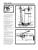
Section 2: Assembly BB L W J V AA V F Figure 2-4A: Attach wheel drive control rod to lever. 1. Remove the vinyl grip (B, Figure 2-6) from the gear select lever (I). Place the wood edge against the edge of the grip and slowly pull off the grip. I E 2. Insert nylon bushing (Z, Figure 2-6) up into console (L). C F 3. Slide spring and washers (J) down onto gear select lever. 4. Insert gear select lever (I) up through nylon bushing (Z) in handlebar console (L).
Section 2: Assembly 9. When shift arm (X) is in neutral position, rotate shift link (P) toward end of gear select lever rod (I). Adjust length of shift link (P) as necessary to fit into hole in bottom of gear select lever (I). NOTE: Pin (K) on Gear Select Lever (I) must be held in the neutral position detent on the shift quadrant (see Figure 2-6) while shift link (P, Figure 2-7) is adjusted. STEP 6: Check Motor Oil Level WARNING 1. Move mower to a level area.
Section 3 Features and Controls WARNING Before operating mower, be sure to read all safety, controls and operating instructions in this Manual and on decals located on machine. Severe personal injury or property damage could result if this instruction is not followed. IMPORTANT: THE MOWER IS EQUIPPED WITH A BLADE-BRAKECLUTCH CONTROL SYSTEM WHICH IS DESIGNED TO STOP THE MOWER BLADES WITHIN THREE (3) SECONDS AFTER RELEASE OF THE OPERATOR PRESENCE CONTROL. THIS SYSTEM WILL STOP THE BLADES BUT NOT THE ENGINE.
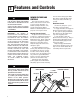
Section 3: Features and Controls Operating Symbols Various symbols are used on the mower to indicate control settings (your model may not have all of the symbols). These symbols are shown below with a description of their meaning. FAST SLOW CHOKE Gear Select Lever Use this lever (C, Figure 3-1) to select any of four forward ground speeds (1 Slow, 2 and 3 - Medium, 4 - Fast), N (Neutral) and R (Reverse). The gear shift pattern is shown in Figure 3-2.
Section 3: Features and Controls Engine Throttle Control This lever (G, Figure 3-6) is used to adjust engine speeds and, on nonElectric Start models, to stop the engine. Always run engine at fast speed setting for best mower performance. The throttle settings are shown below. H – IGNITION/STARTER SWITCH CHOKE - Use when starting a cold engine. FAST - Use during mower operation. Figure 3-6 SLOW - Use when idling engine.
Section 4 Operation WARNING Before operating mower, be sure to read all safety, controls and operating instructions in this Manual and on decals located on machine. Severe personal injury or property damage could result if this instruction is not followed. BEFORE OPERATING MOWER 1. Pre-Operation Checklist With the spark plug wire disconnected from the spark plug, perform the following checks and services before each use: 1. Review Section 1: “Safety” and Section 3, “Features and Controls” in this manual.
Section 4: Operation 3. Test Blade-Brake-Clutch Control System The mower is equipped with a bladebrake-clutch which is designed to stop the mower blades within three (3) seconds after release of the Operator Presence Control or the Blade Drive Control. Never tamper with, or attempt to defeat the purpose of this safety device. The control system is a mechanical device which is subject to wear. Therefore, test the operation of the blade-brake-clutch control system before each use of the mower.
Section 4: Operation 4. To start engine using recoil starter: A. Stand on left side (as viewed from behind handlebars) of machine. Be sure your feet are safely away from the underside of the mower deck and all mower controls are released. Place one foot on top of tire. B. Grasp starter rope handle (Figure 37) and pull slowly until rope pulls slightly harder. Let rope rewind slowly. Then pull rope with a rapid, full arm stroke. Let rope return slowly.
Section 4: Operation C. Put the Gear Select Lever (C, Figure 4-2) in R (reverse) setting by first moving lever to N (neutral). Then pull lever up, turn it to R position, and release lever. D. To start the wheels, slowly squeeze Wheel Drive Control (D, Figure 4-2). To avoid sudden acceleration, slowly squeeze the lever. E. TO STOP THE WHEELS: • To stop drive power to the wheels, release the Wheel Drive Control. The wheels will gradually slow to a stop.
Section 4: Operation BLADE BRAKE CONTROL TEST 3. Start the engine. When the Operator Presence Control is released during operation of the mower, the engine does not stop, but the blades should stop within three (3) seconds. The following test provides a visual test of whether the Blade Brake Control System is functioning. Perform this test before each use of the mower. 4.
Section 5 Maintenance WARNING Before inspecting, cleaning or servicing the machine, shut off engine, wait for moving parts to stop, disconnect spark plug wire and move wire away from spark plug. Remove ignition key (electric start models). Failure to follow these instructions can result in serious personal injury or property damage. Carefully read this Section on mower and engine maintenance and service.
Section 5: Maintenance WARNING Before inspecting, cleaning or servicing the machine, shut off engine, wait for moving parts to stop, disconnect spark plug wire and move wire away from spark plug. Remove ignition key (electric start models). Failure to follow these instructions can result in serious personal injury or property damage. ENGINE CLEANING • Stop engine, wait for parts to stop moving, disconnect spark plug wire, and allow engine to cool before inspecting or cleaning engine.
Section 5: Maintenance WARNING Before inspecting, cleaning or servicing the machine, shut off engine, wait for moving parts to stop, disconnect spark plug wire and move wire away from spark plug. Remove ignition key (electric start models). Failure to follow these instructions can result in serious personal injury or property damage. ENGINE STORAGE If engine will be unused for 30 days or more, prepare it for storage by following the recommended procedures found in the Engine Owner’s Manual.
Section 5: Maintenance WARNING Before inspecting, cleaning or servicing the machine, shut off engine, wait for moving parts to stop, disconnect spark plug wire and move wire away from spark plug. Remove ignition key (electric start models). Failure to follow these instructions can result in serious personal injury or property damage. BLADE DRIVE BELT REPLACEMENT Blade Drive Disengaged Follow this procedure to remove and replace the blade drive belt. An assistant will be needed. A To Remove Belt: 1.
Section 5: Maintenance WARNING Before inspecting, cleaning or servicing the machine, shut off engine, wait for moving parts to stop, disconnect spark plug wire and move wire away from spark plug. Remove ignition key (electric start models). Failure to follow these instructions can result in serious personal injury or property damage. BLADE BRAKE REPLACEMENT Follow this procedure to install a new blade brake. To Remove Blade Brake: 1.
Section 5: Maintenance WARNING Before inspecting, cleaning or servicing the machine, shut off engine, wait for moving parts to stop, disconnect spark plug wire and move wire away from spark plug. Remove ignition key (electric start models). Failure to follow these instructions can result in serious personal injury or property damage. WHEEL DRIVE BELT REPLACEMENT Follow this procedure to replace the wheel drive belt. 1. Stop engine, wait for all parts to stop moving, and disconnect spark plug wire. 2.
Section 5: Maintenance WARNING Before inspecting, cleaning or servicing the machine, shut off engine, wait for moving parts to stop, disconnect spark plug wire and move wire away from spark plug. Remove ignition key (electric start models). Failure to follow these instructions can result in serious personal injury or property damage. E D B Figure 5-12: Wheel drive belt adjustment. M N P O N 3/8"5/16" 2.
Section 5: Maintenance WARNING Before inspecting, cleaning or servicing the machine, shut off engine, wait for moving parts to stop, disconnect spark plug wire and move wire away from spark plug. Remove ignition key (electric start models). Failure to follow these instructions can result in serious personal injury or property damage. I Y Replace if separation begins to form. X P Figure 5-15: Transmission neutral (N) adjustment. MOWER BLADES WARNING Mower blades are sharp.
Section 5: Maintenance WARNING Before inspecting, cleaning or servicing the machine, shut off engine, wait for moving parts to stop, disconnect spark plug wire and move wire away from spark plug. Remove ignition key (electric start models). Failure to follow these instructions can result in serious personal injury or property damage. BATTERY MAINTENANCE DANGER Use extreme caution when working on or near batteries. To help prevent personal injury or property damage:. • Batteries generate explosive gases.
Section 5: Maintenance WARNING Before inspecting, cleaning or servicing the machine, shut off engine, wait for moving parts to stop, disconnect spark plug wire and move wire away from spark plug. Remove ignition key (electric start models). Failure to follow these instructions can result in serious personal injury or property damage. LUBRICATION OFF-SEASON STORAGE Oil and grease the mower according to the recommendations listed in the Lubrication Chart on the next page.
Section 5: Maintenance WARNING Before inspecting, cleaning or servicing the machine, shut off engine, wait for moving parts to stop, disconnect spark plug wire and move wire away from spark plug. Remove ignition key (electric start models). Failure to follow these instructions can result in serious personal injury or property damage. ATTENTION! This chart describes service guidelines only. It does not provide complete service information.
Section 5: Maintenance Before inspecting, cleaning or servicing the machine, shut off engine, wait for moving parts to stop, disconnect spark plug wire and move wire away from spark plug. Remove ignition key (electric start models). Failure to follow these instructions can result in serious personal injury or property damage. Engine malfunction (refer to engine manual). • • • • • Empty fuel tank. Battery or charging malfunction (if applicable). Improperly adjusted or dirty carburetor.
NOTES 41
MANUFACTURER’S LIMITED WARRANTY FOR: The limited warranty set forth below is given by Troy-Bilt LLC with respect to new merchandise purchased and used in the United States, its possessions and territories. “Troy-Bilt” warrants this product against defects in material and workmanship for a period of two (2) years commencing on the date of original purchase and will, at its option, repair or replace, free of charge, any part found to be defective in materials or workmanship.