Safe Operation Practices • Set-Up • Operation • Maintenance • Service • Troubleshooting • Warranty Operator’s Manual LS 27 TB — Log Splitter WARNING READ AND FOLLOW ALL SAFETY RULES AND INSTRUCTIONS IN THIS MANUAL BEFORE ATTEMPTING TO OPERATE THIS MACHINE. FAILURE TO COMPLY WITH THESE INSTRUCTIONS MAY RESULT IN PERSONAL INJURY. TROY-BILT LLC, P.O. BOX 361131 CLEVELAND, OHIO 44136-0019 Printed In USA Form No.
1 To The Owner Thank You Thank you for purchasing a Troy-Bilt Log Splitter. It was carefully engineered to provide excellent performance when properly operated and maintained. If applicable, the power testing information used to establish the power rating of the engine equipped on this machine can be found at www.opei.org or the engine manufacturer’s web site. Please read this entire manual prior to operating the equipment.
2 Important Safe Operation Practices WARNING! This symbol points out important safety instructions which, if not followed, could endanger the personal safety and/or property of yourself and others. Read and follow all instructions in this manual before attempting to operate this machine. Failure to comply with these instructions may result in personal injury. When you see this symbol.
13. If your machine is equipped with an internal combustion engine and is intended for use near any unimproved forest, brush, or grass covered land, the engine exhaust should be equipped with a spark arrestor. Make sure you comply with applicable local, state, and federal codes. Take appropriate firefighting equipment with you. c. Never fuel machine indoors. d. Never remove gas cap or add fuel while the engine is hot or running. e. Allow engine to cool at least two minutes before refueling. 14.
11. When splitting in the vertical position, stabilize the log before moving the control handle. Split as follows: a. Place log on the end plate and turn until it leans against the beam and is stable. b. When splitting extra large or uneven logs, the log must be stabilized with wooden shims or split wood placed between the log and end plate or ground. 12. Always keep fingers away from any cracks that open in the log while splitting. They can quickly close and pinch or amputate your fingers. 13.
Safety Symbols This page depicts and describes safety symbols that may appear on this product. Read, understand, and follow all instructions on the machine before attempting to assemble and operate. Symbol Description READ THE OPERATOR’S MANUAL(S) Read, understand, and follow all instructions in the manual(s) before attempting to assemble and operate WARNING— CRUSHING HAZARD Keep hands away from wedge, end plate, partially split wood and moving parts.
3 Assembly & Set-Up Contents of Carton • One Log Splitter • One Engine Operator’s Manual • One Tongue Assembly NOTE: This Operator’s Manual covers several models. Log splitter features may vary by model. Not all features in this manual are applicable to all log splitter models and the log splitter depicted may differ from yours. 7.
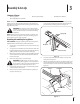
10. Align the holes in the tongue with the holes in the tank bracket and secure with the hardware just removed. See Figure 3-2. 14. Disconnect the dislodger from the beam weld bracket by removing the six hex screws. See Figure 3-4. NOTE: The high pressure hose, which runs from the gear pump to the bottom of the control valve, must be above the tongue assembly. 11. The log splitter is shipped with the beam in a vertical position.
16. Lift and slide the cylinder up to the top of beam and into the weld brackets. See Figure 3-6. Cylinder 20. Cut the metal strap securing the log splitter to the bottom of the crate and remove the wood under the engine and/or any other wood, then roll the log splitter off the bottom of the shipping crate. 21. The control handle is shipped hanging from the valve on the handle link. 22. Remove the clevis pin and bow-tie cotter pin from the control handle. See Figure 3-8.
Set-Up 3. Gas and Oil Fill-Up NOTE: Approved fluids include Shell Tellus® S2 M 32 Hydraulic Fluid, Dexron® III/Mercon® automatic transmission fluid, ProSelect™ AW-32 Hydraulic Oil or 10WAW-ISO viscosity grade 32 hydraulic oil. It is not recommended that fluids be mixed, to top off the reservoir tank during initial set-up use Shell Tellus® S2 M 32 Hydraulic Fluid only. Service the engine with gasoline and oil as instructed in the engine manual packed with your log splitter.
4 Controls & Features Control Handle Cylinder Log Dislodger Horizontal Beam Lock Tongue Beam Assembly End Plate Wedge Jack Stand Vertical Beam Lock Log Tray Figure 4-1 NOTE: This Operator’s Manual covers several models. Log splitter Wedge features may vary by model. Not all features in this manual are The wedge is used to split the wood. applicable to all log splitter models and the log splitter depicted may differ from yours.
5 Operation Starting & Stopping the Engine b. To lock the beam in the vertical position, pull out on the vertical beam lock and rotate it to secure the beam. See Figure 5-2. Refer to the Engine Operator’s manual packed with your log splitter for instructions on starting and stopping the engine. Using the Log Splitter Operating Positions 1. Place the log splitter on flat, dry, solid ground. 2. Block the front and back of both wheels. See Figure 5-1. 2 Vertical 1 Vertical Beam Lock Figure 5-2 5.
Using the Control Handle Splitting the Wood The control handle has three positions. See Figure 5-4. 1. Start the engine as instructed in the Engine Operator’s manual included with the log splitter. 2. Place the log against the end plate and only split the wood in the direction of the grain. 3. To stabilize the log, place your left hand on the side of the log opposite the beam as shown in Figure 5-1.
Operating Tips Transporting the Log Splitter WARNING! Do not tow faster than 45mph and check the local, state and federal requirements before towing on any public road. 1. Lower the beam to its horizontal position. Make certain the beam is locked securely with the horizontal beam lock. 2. Remove the spring clip and clevis pin from the jack stand. 3. Support the tongue and pivot the jack stand up against the tongue. See Figure 5-5. Spring Clip Always: 1.
6 Maintenance & Adjustments WARNING! Do not make any adjustments without stopping the engine, disconnecting the spark plug wire, grounding it against the engine and relieving the hydro system pressure. Always wear safety glasses during operation or while performing any adjustments or repairs. 3. If your engine has a vertical set-up shown in Figure 6-2, refer to Figure 6-2 for changing the hydraulic fluid.
7. Reinstall the cylinder, hoses, pumps, filter and suction hose. Tighten the hose clamps to 50-60 in-lbs. 8. Check the fluid level using the dipstick. Do not overfill. NOTE: Approved fluids include Shell Tellus® S2 M 32 Hydraulic Fluid, Dexron® III / Mercon® automatic transmission fluid, ProSelect™ AW-32 Hydraulic Oil or 10WAW-ISO viscosity grade 32 hydraulic oil. It is recommended that fluids not be mixed. 9.
7 Service Flexible Pump Coupler The flexible pump coupler is a nylon “spider” insert, located between the pump and the engine shaft. Over time, the coupler will harden and deteriorate. Replace the coupler if you detect vibration or noise coming from the area between the engine and the pump. If the coupler fails completely, you will experience a loss of power. NOTE: On vertical shaft engines, it will be neccessary to remove the engine to access the hex screws securing the pump to the engine shaft.
8 Troubleshooting Problem Cylinder rod will not move Slow cylinder shaft speed while extending and retracting Leaking Cylinder 18 Cause Remedy 1. Broken drive shaft. 1. See authorized service dealer. 2. Shipping plugs left in hydraulic hoses. 2. Disconnect hydraulic hoses, remove shipping plugs, reconnect hoses. 3. Set screws in coupling not adjusted properly. 3. See authorized service dealer. 4. Loose shaft coupling. 4. Correct engine/pump alignment as necessary. 5. Gear sections damaged.
Problem Wood will not split or wood splits too slowly Leaking pump shaft seal Cause Remedy 1. Small gear section damaged. 1. See authorized service dealer. 2. Pump check valve leaking. 2. See authorized service dealer. 3. Excessive pump inlet vacuum. 3. Make certain pump inlet hoses are clear and unblocked. 4. Incorrect oil level. 4. Check oil level. 5. Contaminated oil. 5. Drain oil, clean reservoir and refill. 6. Control valve leaking internally. 6. See authorized service dealer. 7.
9 Replacement Parts Component Part Number and Description 737-0348A Vented Dipstick 735-04103 718-04395 718-04392 710-1842A Spider Bushing Coupling, .875 Coupling, .500 Set Screw 723-0405 Hydraulic Oil Filter 737-04308 727-04290 727-04288 727-0443 727-04362 Inlet Filter Inlet Hose Hydro Hose Return Hose Hydro Hose 726-0132 Hose Clamp 634-0186 Complete Wheel, 16.0 x 4.8 x 8.
Notes 10 21
Section 10— Notes
Section 10 — Notes 23
MANUFACTURER’S LIMITED WARRANTY FOR The limited warranty set forth below is given by Troy-Bilt LLC with respect to new merchandise purchased and used in the United States and/or its territories and possessions, and by MTD Products Limited with respect to new merchandise purchased and used in Canada and/ or its territories and possessions (either entity respectively, “Troy-Bilt”). This warranty is in addition to any applicable emissions warranty provided with your product.
Medidas importantes de seguridad • Configuración • Funcionamiento • Mantenimiento • Servicio • Solución de problemas • Garantía Manual del Operador LS 27 TB — Máquina rompe troncos ADVERTENCIA LEA Y RESPETE TODAS LAS NORMAS DE SEGURIDAD E INSTRUCCIONES INCLUIDAS EN ESTE MANUAL ANTES DE PONER EN FUNCIONAMIENTO ESTA MÁQUINA. SI NO RESPETA ESTAS INSTRUCCIONES PUEDE PROVOCAR LESIONES PERSONALES. TROY-BILT LLC, P.O. BOX 361131 CLEVELAND, OHIO 44136-0019 Impreso en Estados Unidos de América Formulario No.
Al propietario 1 Gracias Gracias por comprar una MTD máquina rompe troncos. La misma ha sido diseñada cuidadosamente para brindar excelente rendimiento si se la opera y mantiene correctamente. Por favor lea todo este manual antes de operar el equipo. Le indica cómo configurar, operar y mantener la máquina con seguridad y fácilmente. Por favor asegúrese de seguir cuidadosamente y en todo momento las prácticas de seguridad recomendadas, y hacérselas seguir a cualquier otra persona que opere la máquina.
2 Medidas importantes de seguridad ADVERTENCIA: La presencia de este símbolo indica que se trata de instrucciones de seguridad importantes que se deben respetar para evitar poner en peligro su seguridad personal y/o material y la de otras personas. Lea y cumpla todas las instrucciones de este manual antes de intentar operar esta máquina. Si no respeta estas instrucciones puede provocar lesiones personales. Cuando vea este símbolo.
13. Si la máquina está equipada con un motor de combustión interna y existe la intención de usarla cerca de un terreno agreste cubierto de bosque, arbustos o pasto, el escape del motor debe estar provisto de un amortiguador de chispas. Asegúrese de respetar todos los códigos locales, estatales y federales aplicables. Lleve el equipamiento adecuado para combatir incendios. a. Utilice sólo los recipientes para gasolina autorizados. b.
8. Use únicamente la mano derecha para operar los controles. 9. Nunca intente cortar más de un tronco a la vez. 10. Para los registros que no están cortados en ángulo recto, el extremo menos cuadrado de la sesión se debe colocar hacia el rayo y la cuña, y el extremo cuadrado colocado hacia la placa terminal. 11. Cuando corte en posición vertical, estabilice el tronco antes de mover la manija de control. Corte según se indica a continuación: 4.
Símbolos de seguridad En esta página se presentan y describen los símbolos de seguridad que pueden aparecer en este producto. Lea, entienda y cumpla todas las instrucciones incluidas en la máquina antes de intentar realizar el montaje de la unidad y utilizarla. Símbolo Descripción LEA LOS MANUALES DEL OPERADOR Lea, entienda y cumpla todas las instrucciones incluidas en los manuales antes de realizar el montaje de la unidad y utilizarla.
3 Montaje y Configuración Contenido de la caja • Una máquina rompetroncos • Un Manual del operador del motor • Un montaje de lengüeta NOTE: Ce manuel utilisateur couvre plusieurs modèles. Caractéristiques máquina rompe troncos peut varier selon le modèle. Toutes les fonctionnalités de ce manuel sont applicables à tous les modèles máquina rompe troncos et wáquina rompe troncos représenté peut différer de la vôtre.  7.
10. Alinee los orificios de la lengüeta con los orificios del soporte del tanque y fíjela con los elementos de ferretería que se acaban de retirar. Vea la Figura 3-2. 14. Desconecte el liberador del soporte soldado de vigueta retirando los seis tornillos hexagonales. Vea la Figura 3-4. Tornillos de cabeza hexagonal NOTA: La manguera de alta presión, que se extiende desde la bomba de engranaje hasta la parte inferior de la válvula de control, debe estar por encima del conjunto de la lengüeta. 11.
16. Levante y deslice el cilindro hacia arriba hasta el tope de la vigueta y dentro de los soportes soldados. Vea la Figura 3-6. Cilindro 20. Corte la tira de metal que sujeta la máquina rompetroncos a la base de la aja y extraiga la madera que está debajo del motor y/o cualquier otra madera, luego haga rodar la máquina fuera de la base de la caja de embalaje. 21. La manija de control se envía colgando de la válvula en el enlace de la manija. 22.
Presión de los neumáticos 5. La presión de operación máxima recomendada es 30 psi. En ninguna circunstancia supere la presión en psi recomendada por el fabricante. Mantenga la misma presión en todos los neumáticos. Desconecte la bujía y cebe la bomba tirando del arrancador de retroceso hasta el máximo. Repita este paso aproximadamente 10 veces. 6. Vuelva a conectar el cable de la bujía y arranque el motor según las instrucciones del manual del operador del motor. 7.
Controles y Características Cilindro 4 Liberador de la madera Manija de control Bloqueo de la viga horizontal Lengüeta Montaje de la vigueta Fin del mural Cuña Gato Vertical: Vigueta Tuerca Bandeja de troncos NOTE: Ce manuel utilisateur couvre plusieurs modèles. Caractéristiques máquina rompe troncos peut varier selon le modèle. Toutes les fonctionnalités de ce manuel sont applicables à tous les modèles máquina rompe troncos et wáquina rompe troncos représenté peut différer de la vôtre.
5 Funcionamiento Arranque y detención del motor b. Para trabar la vigueta en posición vertical, tire del bloqueo de vigueta vertical hacia afuera y gírelo para ajustar la vigueta. Vea la Figura 5-2. Consulte el manual del operador del motor embalado con la máquina rompetroncos por las instrucciones sobre cómo arrancar y detener el motor. Uso de la máquina rompetroncos Posiciones de operación 1. Coloque la máquina rompetroncos sobre suelo nivelado, seco y resistente. 2.
Uso de la manija de control Cómo cortar madera La manija de control tiene tres posiciones. Vea la Figura 5-4. 1. Ponga en marcha el motor como se indica en el manual del operador del motor que se incluye con la máquina rompetroncos. 2. Coloque el tronco contra la placa del extremo y solamente corte la madera en la dirección de la veta. 3. Para estabilizar el tronco, coloque la mano izquierda en el costado del tronco que está frente a la viga como se indica en la Figura 5-1.
Transporte de la máquina rompetroncos Consejos de operación 1. Siempre: Baje la vigueta a la posición horizontal. Asegúrese de que la vigueta esté trabada firmemente con el bloqueo de vigueta horizontal. 2. Retire la abrazadera de resorte y el pasador de horquilla del gato. 3. Sostenga la lengüeta y gire el gato hacia arriba contra la lengüeta. Vea la Figura 5-5. Abrazadera de resorte Pasador de horquilla Gato Figura 5-5 4.
6 Maintenance & Adjustments ¡ADVERTENCIA! Siempre detenga el motor, desconecte el cable de la bujía y haga masa contra el motor antes de realizar cualquier ajuste. Utilice siempre anteojos de seguridad durante el funcionamiento o mientras ajusta o repara este equipo. 2. Si el motor tiene un motor horizontal de configuración se muestra en la Figura 6-1, consulte la Figura 6-1 para cambiar el aceite hidráulico.
5. Con mucho cuidado desenrosque el filtro de entrada y limpiarlo con aceite penetrante. Vea la Figura 6-3. 13. Si Rellene el depósito necesario dentro del rango marcado en la varilla. Vea la Figura 6-4. Varilla MAX MIN Filtro de entrada Sólo de fluidos hidráulicos Figura 6-3 6. Deje que el líquido drene en un recipiente adecuado. Figura 6-4 14. NOTA: El tanque de almacenamiento tiene una capacidad de 3 galones y todo el sistema hidráulico tiene una capacidad de aproximadamente 4,7 galones. 7.
Almacenamiento fuera de temporada Si el rompe troncos no se usa por más de 30 días, prepárelo para su almacenamiento de la siguiente manera: ¡ADVERTENCIA! Nunca almacene la máquina con combustible en el tanque en un área del edificio donde los vapores puedan alcanzar una llama expuesta o chispas, o donde existan fuentes de ignición, tales como calentadores de agua, calefactores de ambientes, hornos, secadoras de ropa, estufas, motores eléctricos, etc. 1.
7 Service Acoplador flexible de la bomba El acoplador flexible de la bomba es un inserto de nylon “araña”, situado entre la bomba y el eje del motor. Con el tiempo, el acoplador se endurece y se deterioran. Reemplazar el acoplador si detecta la vibración o el ruido procedente de la zona entre el motor y la bomba. Si el acoplamiento falla por completo, usted experimentará una pérdida de poder.
Solución de Problemas Problema La varilla del cilindro no se mueve Velocidad lenta del eje del cilindro durante la extensión o retracción. Cilindro con pérdidas 8 Causa Solución 1. El eje de accionamiento está roto. 1. Consulte al distribuidor de servicio autorizado. 2. Se han dejado los tapones de envío en las mangueras hidráulicas. 2. Desconecte las mangueras hidráulicas, retire los tapones colocados para el envío, vuelva a conectar las mangueras. 3.
Problema Causa La madera no se parte o se divide la madera con demasiada lentitud 1. La sección de engranajes pequeños está dañada. 1. Consulte al distribuidor de servicio autorizado. 2. La válvula de retención de la bomba tiene pérdidas. 2. Consulte al distribuidor de servicio autorizado. 3. Vacío excesivo en la entrada de la bomba. 3. Asegúrese de que las mangueras de entrada estén despejadas y sin bloqueos. 4. El nivel de aceite es incorrecto. 4. Revise el nivel de aceite. 5.
Notas 9 21
22 Sección 9— Notas
Sección 9 — Notas 23
GARANTÍA LIMITADA DEL FABRICANTE PARA La siguiente garantía limitada es otorgada por Troy-Bilt LLC con respecto a nuevos productos adquiridos y utilizados en Estados Unidos y/o sus territorios y posesiones, y por MTD Products Limited con respecto a nuevos productos adquiridos y utilizados en Canadá y/o sus territorios y posesiones (cualquiera de las dos entidades, respectivamente, “Troy-Bilt”). Esta garantía es adicional a la garantía de emisiones aplicables proporcionada con el producto.