Important Safe Operation Practices • Assembly & Set-Up • Controls & Operation • Product Care Operator’s Manual Zero-Turn Tractor Lapbar Table of Contents Important Safe Operation Practices...................... 2 Product Care............................................................15 Assembly & Set-Up................................................... 6 Parts/Warranty............... See Separate Supplement Controls & Operation...............................................
Important Safe Operation Practices 2 WARNING This symbol points out important safety instructions which, if not followed, could endanger the personal safety and/or property of yourself and others. Read and follow all instructions in this manual before attempting to operate this machine. Failure to comply with these instructions may result in personal injury. When you see this symbol.
6. Keep all movement on the slopes slow and gradual. Do not make sudden changes in speed or direction. Rapid acceleration or deceleration could cause the front of the machine to lift and rapidly roll over backwards, which could cause serious injury. Do Not: 1. Do not turn on slopes unless necessary; then turn slowly uphill and use extra care while turning. 2. Do not mow near drop-offs, ditches or embankments.
Do not modify engine To avoid serious injury or death, do not modify engine in any way. Tampering with the governor setting can lead to a runaway engine and cause it to operate at unsafe speeds. Never tamper with factory setting of engine governor.
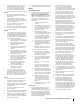
(OK) Figure 1 Slope Gauge ne d a s h e d li 15° Slope 15° USE THIS SLOPE GAUGE TO DETERMINE IF A SLOPE IS TOO STEEP FOR SAFE OPERATION! To check the slope, proceed as follows: 1. Remove this page and fold along the dashed line. 2. Locate a vertical object on or behind the slope (e.g. a pole, building, fence, tree, etc.) 3. Align either side of the slope gauge with the object (See Figure 1 and Figure 2 ). 4. Adjust gauge up or down until the left corner touches the slope (See Figure 1 and Figure 2). 5.
2 Assembly & Set-Up Thank You Thank you for purchasing this product. It was carefully engineered to provide excellent performance when properly operated and maintained. Please read this entire manual prior to operating the equipment. It instructs you how to safely and easily set up, operate and maintain your machine. Please be sure that you, and any other persons who will operate the machine, carefully follow the recommended safety practices at all times.
Position Drive Control Levers 3. The drive control levers of the tractor are lowered for shipping purposes. The hex screws and flat washers that normally secure the control levers in their operating position are in a hardware pack inside your manual bag. The control levers must be repositioned to operate the tractor. To reposition the control levers for operation, proceed as follows: 1. Place the chute deflector on the deck, be sure to insert the tabs on the chute deflector into the holes on the deck.
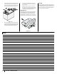
1. Remove the plastic cover, if present, from the positive battery terminal and attach the red cable to the positive battery terminal (+) with the bolt (a) and hex nut (b). See Figure 2-10. (b) (b) (a) (c) (a) 3. Position the red rubber boot (c) over the positive battery terminal to help protect it from corrosion. Note: If the battery is put into service after the date shown on top/side of battery, charge the battery as instructed in the Product Care section prior to operating the tractor.
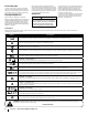
3 Controls & Operation (A) (E †) (A) (C) (B) (C) (B) (L) † (I) (E) (N) † (D) (L) † (M) † (K) (E †) (D) G (J) G (N) † (J) (K) (H) (H) (F) (F) † -- If Equipped Figure 3-1 Note: This Operator’s Manual covers several models. Tractor features may vary by model. Not all features in this manual are applicable to all tractor models and the tractor depicted may differ from yours.
Transmission Bypass Rods (F) Throttle Control (If equipped) The transmission bypass rods (one for each the RH and LH transmission) are located on the rear of the tractor, just inside each rear wheel. When engaged, the two rods open a bypass within the hydrostatic transmissions, which allows the tractor to be pushed short distances by hand. Refer to the Assembly & Set-Up section for instructions on using the bypass feature. When set in a given position, a uniform engine speed will be maintained.
Operation • Methyl Tertiary Butyl Ether (MTBE) and unleaded gasoline blends (up to a maximum of 15% MTBE by volume) are approved fuels. Other gasoline/ether blends are not approved. Check the engine oil level. Clean the air cleaner element if necessary. Check the tire inflation pressures. Adjust the seat for operator’s maximum comfort, visibility and for maintaining complete control of the tractor.
4. Note: Lap bars must be moved fully inward before pushing forward or backward to ensure brakes are fully disengaged. Parking the tractor on uneven terrain or a hill may cause the brakes to bind and not release fully. In this case the tractor will not drive when the lap bars are moved. If this happens, move the lap bar in the opposite direction slightly to take the load off the brakes and allow them to release fully.
Driving the Tractor In Reverse 2. WARNING To turn to the right while traveling in reverse, move the right drive control lever forward of the left drive control lever. See Figure 3-9. Always look behind and down on both sides of the tractor before backing up. Always look behind while traveling in the reverse direction. 1. Slowly and evenly move both drive control levers rearward. The tractor will start to move in the reverse direction. See Figure 3-7. 3.
Stopping the Tractor Note: When operating the tractor be certain that the throttle is always in the FAST position. Operating with the throttle at less than full throttle may lead to premature battery wear and a poor quality cut. 1. Move both drive control levers to the neutral position to stop the motion of the tractor. 2. Push the PTO downward to the OFF position. 3. Use the deck lift handle to raise the deck to its highest position. 3. 4.
4 Product Care Maintenance Schedule Before Each use Check Engine Oil Level Check & Clean Transmission Cooling Slots Check Air Filter for Dirty, Loose or Damaged Parts After First 5 Hours Every 10 Hours Every 25 Hours Every 50 Hours Every 100 Hours P P P P P P P P P Grease All Lubrication Points Check Intake Screen/Clean as Needed Check Blades/Sharpen or Replace as Needed Check Tire Pressure Check/Clean Underside of Deck P P P P P P P Inspect & Lube Deck Wheels Check Deck Level/Pitch P P P Check
Note: This Operator’s Manual covers several models. Tractor features may vary by model. Not all features in this manual are applicable to all tractor models and the tractor depicted may differ from yours. 3. Troubleshooting 4. Place an appropriate oil collection container with at least a 2.5 quart capacity below the opening of the oil drain tube, to collect the used oil. Remove the oil fill cap/dipstick from the oil fill tube.
Lubrication • WARNING Before lubricating, repairing, or inspecting, always disengage PTO, set parking brake, stop engine and remove key to prevent unintended starting. • Using a pressure lubricating gun, lubricate the front castor wheel axles with grease after every 10 hours of service. • Periodically lubricate all other pivot points with a quality lubricating oil.
5. Lubricate all lubrication points. 5. Note: Using a pressure washer or garden hose is not recommended for cleaning your tractor. It may cause damage to electrical components, spindles, pulleys, bearings or the engine. The use of water will result in shortened life and reduce serviceability. To adjust the drive control levers forward/ rearward, proceed as follows: 1. Removing The Tractor From Storage If you are going to adjust the control levers forward or rearward, proceed to the next step.
Off-Season Storage Adjusting the Deck Wheels WARNING Keep hands and feet away from the discharge opening of the cutting deck. Note: The deck wheels are an anti-scalp feature of the deck and are not designed to support the weight of the cutting deck. The deck wheels should be approximately 1⁄4-1⁄2” above the ground when the deck is set in the desired height setting. To adjust the deck wheels see the Assembly & Set-Up section for instructions.
Charging the Battery 3. Remove the hex washer screw (a), flat washer (b) securing the belt keeper rod (c) to the transmission mount brackets (d) and remove the belt keeper rod (c). See Figure 4-12. Test and, if necessary, recharge the battery after the tractor has been stored for a period of time. • A voltmeter or load tester should read 12.6 volts (DC) or higher across the battery terminals. See Figure 4-11. Voltmeter Reading State of Charge Charging Time 12.7 100% Full Charge 12.4 75% 90 Min.
d. While still holding the PTO belt (a) downward, continue turning the PTO pulley (b) until the PTO belt (a) is rolled off the PTO pulley (b). Refer to Figure 4-17. (a) (b) (a) 9. Figure 4-17 e. Lower the deck into the lowest mowing position using the deck lift handle. See Figure 4-14. f. Move on to step 9. Pull the cotter pin (a) out of the front deck lift rod (b) securing it to the deck. See Figure 4-18. Slide the deck lift rod out of the front hanger bracket (c).
Note: Take note of the position of the belt guards (c) to ensure they are properly reinstalled. Note: On some decks it may be necessary to remove the spindle covers to remove and/or install the new belt. To remove the spindle covers, remove the screws securing them to the deck. 3. Carefully remove the belt from around the idler pulleys (a & b) and the spindle pulleys (d). 4. Install the new belt pulleys as shown and reinstall the belt covers. 5.
Medidas importantes de seguridad • Armado e instalación • Controles y funcionamiento • Cuidado del producto Manual del Operador Tractor de radio de giro cero Barra de seguridad Índice Medidas importantes de seguridad....................... 2 Armado einstalación............................................... 6 Controles y Funcionamiento................................... 9 Cuidado del producto.............................................15 Piezas/Garantía..................
Medidas de seguridad importantes 2 ADVERTENCIA Este símbolo indica instrucciones de seguridad importantes que, de no seguirse, podrían poner en peligro la seguridad personal y/o la propiedad suya y de terceros. Lea y cumpla todas las instrucciones de este manual antes de intentar hacer funcionar esta máquina. Si no sigue estas instrucciones, se pueden provocar lesiones personales. Cuando vea este símbolo. TENGA EN CUENTA LA ADVERTENCIA.
6. Haga que todos los movimientos en las pendientes sean lentos y graduales. No realice cambios bruscos de velocidad o dirección. La aceleración o la reducción repentina de velocidad pueden hacer que el frente de la máquina se levante y vuelque hacia atrás, lo que podría producir lesiones graves. No: 1. 2. No gire en pendiente a menos que sea necesario; si lo hace, gire lentamente cuesta arriba y tenga sumo cuidado al hacerlo. 6. Desplácese lentamente y deje distancia adicional para detenerse. 7.
No modifique el motor Para evitar lesiones graves o la muerte, no modifique el motor de ninguna manera. La manipulación del ajuste del regulador puede modificar la regulación del motor y hacer que este funcione a velocidades inseguras. Nunca manipule el ajuste de fábrica del regulador del motor.
(OK) Figura 1 Indicador de pendiente de Pendiente de 15° Línea Figura 2 (MUY EMPINADA) 5° pu n t o s a1 ¡USE ESTE INDICADOR DE PENDIENTE PARA DETERMINAR SI UNA PENDIENTE ES DEMASIADO EMPINADA PARA SU SEGURIDAD! Para comprobar la pendiente, proceda de la siguiente manera: 1. Separe esta página y pliéguela por la línea de puntos. 2. Ubique un objeto vertical que se encuentre sobre o detrás de la pendiente (un poste, un edificio, un cerco, un árbol, etc.) 3.
2 Montaje y Configuración Muchas gracias Gracias por comprar este producto. Ha sido cuidadosamente diseñado para brindar excelente rendimiento si se lo hace funcionar y se lo mantiene correctamente. Por favor lea todo este manual antes de hacer funcionar el equipo. El manual le indica cómo configurar, hacer funcionar y mantener la máquina de manera fácil y segura.
Coloque las palancas de control de la transmisión en posición 3. Las palancas de control de la transmisión del tractor se bajan para el embarque. Los tornillos hexagonales y arandelas planas que normalmente aseguran las palancas de control en su posición de funcionamiento están en un paquete de herrajes dentro de la bolsa de su manual. Las palancas de control se deben volver a colocar en su posición para hacer funcionar el tractor.
1. Retire la cubierta plástica, si está presente, del borne positivo de la batería y una el cable rojo al borne positivo de la batería (+) utilizando el perno (a) y la tuerca hexagonal (b). Consulte la Figura 2-10. (b) Nota: Si la batería se pone en funcionamiento después de la fecha indicada en su parte superior o al costado de la misma, cárguela siguiendo las instrucciones de la página 8 de la sección Cuidado del producto de este manual antes de operar el tractor.
3 Controles y Funcionamiento (A) (E †) (A) (C) (B) (C) (B) (L) † (I) (E) (N) † (D) (L) † (M) † (K) (E †) (D) G (J) G (N) † (J) (K) (H) (H) (F) (F) † -- Si está equipado Figura 3-1 Nota: Este manual de operación corresponde a varios modelos. Las características del tractor pueden variar según los modelos. No todas las características que se incluyen en este manual se aplican a todos los modelos de tractor y la máquina que se ilustra aquí puede diferir de la suya.
Varillas de derivación de la transmisión (F) Las varillas de derivación de la transmisión (una para cada transmisión, lado derecho y lado izquierdo) están ubicadas en la parte trasera del tractor, justo dentro de cada rueda trasera. Cuando están engranadas, las dos varillas abren una derivación dentro de las transmisiones hidrostáticas, lo cual permite empujar el tractor a mano a lo largo de distancias cortas.
Funcionamiento Seguridad general • • • • • • • • • • • • • • RECIBA LAS INSTRUCCIONES - Lea este manual del operador en su totalidad. Aprenda a usar esta máquina DE MANERA SEGURA. No se arriesgue a quedar expuesto a LESIONES o a la MUERTE. Solamente se debe permitir operar este tractor a quienes se hayan familiarizado a fondo con el uso del mismo. Antes de arrancar el motor o de empezar a operar, familiarícese con los controles. El operador debe estar en el asiento del operador.
4. Nota: Las barras de seguridad se deben mover Haga controlar y reparar el sistema eléctrico del tractor lo más pronto que fuere posible, para eliminar la necesidad de usar cables de puente para arrancarlo. totalmente hacia adentro antes de empujar hacia adelante o hacia atrás a fin de asegurarse de que los frenos estén totalmente liberados. Si estaciona el tractor en un terreno desparejo o en una colina, esto puede hacer que los frenos se agarren y no se suelten por completo.
Conducción del tractor en marcha atrás 2. ADVERTENCIA Para girar a la derecha mientras se desplaza marcha atrás, mueva la palanca de control del lado derecho hacia adelante respecto de la palanca izquierda de control de la transmisión. Consulte la Figura 3-9. Siempre mire hacia atrás y hacia abajo a ambos lados del tractor antes de desplazarse marcha atrás. Siempre mire hacia atrás cuando se desplaza en marcha atrás. 1. 3. 4. Mueva las dos palancas de control lenta y suavemente hacia atrás.
Detención del tractor 1. Mueva las dos palancas de control a la posición neutral para detener el movimiento del tractor. 2. Empuje la PTO hacia abajo, hasta la posición OFF (apagado). 3. Use la manija de elevación de la plataforma para levantar la plataforma a su posición más alta. 4.
4 Cuidado del producto Programa de mantenimiento Antes de cada uso Controle el nivel de aceite del motor Verifique y limpie las ranuras de enfriamiento de la transmisión Revise si el filtro de aire está sucio, flojo o tiene piezas dañadas Después de las primeras 5 horas Cada 10 horas Cada 25 horas Cada 50 horas Cada 100 horas P P P P P P P P P Engrase todos los puntos de lubricación Revise el filtro de admisión/limpie si corresponde Revise las cuchillas/afile o reemplace si corresponde Revise la pre
Nota: Este manual de operación corresponde a varios modelos. Las características del tractor pueden variar según los modelos. No todas las características que se incluyen en este manual se aplican a todos los modelos de tractor y la máquina que se ilustra aquí puede diferir de la suya. 3. Para recoger el aceite usado, coloque un recipiente adecuado para recolectar el aceite, con al menos una capacidad de 2.5 cuartos de galón, debajo de la abertura del tubo de drenaje de aceite.
Lubricación Información general sobre la batería ADVERTENCIA ADVERTENCIA Antes de lubricar, reparar o inspeccionar, desconecte la toma de fuerza (PTO), ponga el freno de mano, pare el motor y retire la llave, para evitar el encendido accidental del motor. • Con una pistola de lubricación a presión, lubrique los ejes de las ruedas pivotantes delanteras con grasa cada 10 horas de servicio. • Lubrique periódicamente todos los otros puntos de pivote con un aceite lubricante de calidad.
Retiro del tractor del lugar de guarda Para ajustar las palancas de control hacia adelante o hacia atrás, proceda de la siguiente forma: 1. Inspeccione el aceite del motor. 2. Cargue totalmente la batería e infle los neumáticos a la presión recomendada. 3. Llene el depósito de combustible con gasolina limpia y nueva. 4. Arranque el motor y déjelo andar en ralentí unos cuantos minutos para asegurar que su funcionamiento sea adecuado. 5.
Ajuste de las ruedas de la plataforma ADVERTENCIA Mantenga las manos y los pies alejados de la abertura de descarga de la plataforma de corte. Nota: Las ruedas de la plataforma constituyen un mecanismo para el cuidado del césped y no fueron diseñadas para soportar el peso de la plataforma de corte. Las ruedas de la plataforma deben estar aproximadamente entre 1⁄4-1⁄2 in por encima del nivel del suelo cuando la plataforma se fija en el valor de altura deseado.
Carga de la batería 3. • Un voltímetro o medidor de carga debería dar una lectura de 12,6 voltios (CC) o más en todos los bornes de la batería. Consulte la Figura 4-11. Voltímetro (lectura) Estado de la carga Tiempo de carga 12,7 100% Carga completa 12,4 75% 90 min 12,2 50% 180 min 12,0 25% 280 min Figura 4-11 • Cargue la batería con un cargador de batería de 12 voltios a un MÁXIMO de 10 amperios. b.
d. Mientras sostiene la correa de la PTO (a) hacia abajo, siga girando la polea de la PTO (b) hasta que la correa de la PTO (a) se deslice fuera de la polea (b). Consulte la Figura 4-17. (a) Instalación de la plataforma Instale la plataforma sobre el tractor de la siguiente forma: 1. Ubique la manija de elevación de la plataforma en la posición de corte más elevada. Vea la Figura 4-14. 2. .Figura 4-14.
Nota: Tome nota de la posición de la protección de correa (c) para asegurar que se haya vuelto a instalar de manera correcta. Nota: En algunas plataformas puede ser necesario retirar las cubiertas de los husillos para sacar y/o instalar la correa nueva. Para retirar las cubiertas de los husillos, saque los tornillos que los sujetan a la plataforma. 3. Extraiga con cuidado la correa de alrededor de las poleas locas (a y b) y de las poleas del husillo. 4.