Safe Operation Practices • Set-Up • Operation • Maintenance • Service • Troubleshooting • Warranty Operator’s Manual Pony, Pony ES & Pro-Line FRT Tiller WARNING READ AND FOLLOW ALL SAFETY RULES AND INSTRUCTIONS IN THIS MANUAL BEFORE ATTEMPTING TO OPERATE THIS MACHINE. FAILURE TO COMPLY WITH THESE INSTRUCTIONS MAY RESULT IN PERSONAL INJURY. TROY-BILT LLC, P.O. BOX 361131 CLEVELAND, OHIO 44136-0019 Printed In USA Form No.
1 To The Owner Thank You Thank you for purchasing a Troy-Bilt Garden Tiller. It was carefully engineered to provide excellent performance when properly operated and maintained. If applicable, the power testing information used to establish the power rating of the engine equipped on this machine can be found at www.opei.org or the engine manufacturer’s web site. Please read this entire manual prior to operating the equipment.
2 Important Safe Operation Practices WARNING! This symbol points out important safety instructions which, if not followed, could endanger the personal safety and/or property of yourself and others. Read and follow all instructions in this manual before attempting to operate this machine. Failure to comply with these instructions may result in personal injury. When you see this symbol.
c. When practical, remove gas-powered equipment from the truck or trailer and refuel it on the ground. If this is not possible, then refuel such equipment on a trailer with a portable container, rather than from a gasoline dispenser nozzle. 11. After striking a foreign object, stop the engine, disconnect the spark plug wire and ground against the engine. Thoroughly inspect the machine for any damage. Repair the damage before starting and operating. d.
9. If the fuel tank has to be drained, do this outdoors. 10. Observe proper disposal laws and regulations for gas, oil, etc. to protect the environment. 11. According to the Consumer Products Safety Commission (CPSC) and the U.S. Environmental Protection Agency (EPA), this product has an Average Useful Life of seven (7) years, or 130 hours of operation.
Safety Symbols This page depicts and describes safety symbols that may appear on this product. Read, understand, and follow all instructions on the machine before attempting to assemble and operate. Symbol Description READ THE OPERATOR’S MANUAL(S) Read, understand, and follow all instructions in the manual(s) before attempting to assemble and operate WARNING— ROTATING TINES Do not put hands or feet near rotating parts. Contact with the rotating parts can amputate hands and feet.
3 Assembly & Set-Up Contents of Carton • One Tiller • One Handlebar Support • One Handlebar Assembly • One Hardware Pack • One Operator’s Manual • One Engine Operator’s Manual WARNING! To prevent personal injury or property damage, do not start the engine until all assembly steps are complete and you have read and understand the safety and operating instructions.
3. Gently lift the handlebar (do not overstretch the attached cable) and place the handlebar cross-brace in front of the curved height adjustment bracket. See Fig. 3-2. 6. On electric start machines, reattach the height adjustment bracket. Tighten both screws securely. Make sure the handlebar cross-brace is under the bracket. 7. Move the handlebars up or down to align the threaded hole in the cross brace with one of the four slots in the curved height adjustment bracket.
Reverse Clutch Control Forward Clutch Cable 1. 1. Carefully unwrap the reverse clutch control cable from its shipping position and route it up along the inside edge of the left side handlebar. See Fig. 3-5. A knob and large hex nut is installed on the cable. Remove any fasteners (rubber bands, tape, etc.) that may secure the Forward Clutch Control levers to the handlebar. See Fig. 3-6.
3. Attach the cable adjuster to the bracket on the right-side handlebar. See Fig. 3-8. Use the two 1⁄2” wrenches to loosen the two jam nuts just enough to slide the cable adjuster onto the bracket. Then hand tighten the jam nuts. 2. Insert two #10-32 x 1⁄2” round head screws down through the “+” marks on the control panel decal and securely attach the wheel gear mounting bracket using two #10 lockwashers and #10-32 nuts. 3. Use a small board to tap the Wheel Gear Lever knob securely onto the lever. 4.
4 Controls & Features Reverse Clutch Control Wheel Gear Lever Forward Clutch Control Lever Handlebar Height Adjustment Screw Forward Clutch Control Lever Depth Regulator Lever Figure 4-1 Tillers controls and features are described below and illustrated Depth Regulator in Fig. 4-1. The Depth Regulator lever controls the tilling depth of the tines.
5 Operation Starting the Engine 9. For electric starting models: a. Pre-Start Checklist With the spark plug wire disconnected from the spark plug, make the following checks and perform the following services before starting the engine. 1. Read the Safe Operation Practices and Features & Controls Sections in this manual. Read the separate Engine Operator’s Manual. 2. Check the machine for loose or missing hardware. Service as required. 3. Check the engine oil level. See Engine Operator’s Manual. 4.
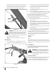
Engaging the Drive & Tines 1. 2. For forward motion of the wheels and tines: a. Pull one or both of the Forward Clutch Control Levers up and hold them against the handlebars. To stop the forward motion of the wheels and tines, release the levers. b. As the tiller moves forward, relax and let the wheels pull the machine along while the tines dig. Walk behind and a little to one side of the tiller. Use a light but secure grip with one hand on the handlebars, and keep your arm loose. See Fig. 5-1.
3. With the tiller balanced, push sideways on the handlebar to move the tiller in the direction of the turn. See Fig. 5-4. After completing the turn, slowly lower the tines into the soil and increase the engine speed. Let the Tiller Do the Work • While tilling, relax and let the wheels pull the tiller along while the tines do the digging. Walk on the side that is not yet finished to avoid making footprints in the freshly tilled soil and lightly, but securely grip the handlebar with just one hand.
Suggested tilling patterns • • When preparing a seedbed, go over the same path twice in the first row, then overlap one-half the tiller width on the rest of the passes. See Fig. 5-5. If the garden size will not permit lengthwise and then crosswise tilling, then overlap the first passes by one-half a tiller width, followed by successive passes at one-quarter width See Fig. 5-7. 1 2 3 Figure 5-7 Figure 5-5 • When finished tilling in one direction, make a second pass at a right angle as shown in Fig.
Tilling on slopes • To create a terrace, start at the top of the slope and work down. Go back and forth across the first row as shown in Fig. 5-9. If you must garden on a moderate slope, please follow two very important guidelines: 1. Till only on moderate slopes, never on steep ground where the footing is difficult. Review the safety rules in the Safe Operation Practices Section. 2. It is recommended to till up and down the slopes rather than terracing.
Power Composting • WARNING! When power composting, do not keep the Depth Regulator Lever at a deep setting if the tiller jumps or bucks. If jumping or bucking occurs, move the Depth Regulator Lever down to one of the shallower settings and then slowly increase the tilling depth on later passes. Failure to follow this warning could result in personal injury.
6 Maintenance & Adjustments Maintenance Schedule After 2-hour break-in Before Each Use Every 5 Hours Every 10 Hours P Clean Engine Check Drive Belt Tension Check Nuts and Bolts P P P P P Lubricate Tiller Check Transmission Gear Oil P P P P Check Tines for Wear Check Air Pressure in Tires WARNING! Before inspecting, cleaning or servicing the machine, shut off the engine, wait for all the moving parts to come to a complete stop, disconnect the spark plug wire and move the wire away from the spark
4. If oil does not flow from the check hole, add oil as follows: NOTE: Do not use automatic transmission fluid or motor oil in the transmission. a. Clean the area around the fill hole and unscrew the gear oil fill plug. b. If adding only a few ounces of gear oil, use API rated GL-4 or GL-5 gear oil having a viscosity of SAE 140, SAE 85W-140 or SAE 80W-90. If refilling an empty transmission, use only GL-4 gear oil having a viscosity of SAE 85W-140 or SAE 140. c.
Tension on a new forward clutch belt should be checked after the first two (2) hours of operation and after every ten (10) hours of operation after that. See Fig. 6-4. 2. Belt adjustments are done with the forward clutch cable adjuster. Use two 1⁄2”, open-end wrenches to loosen the two jam nuts a few turns. See Fig. 6-6 Cable Adjuster Forward Clutch Belt Jam Nuts Figure 6-4 1. 2.
1. 2. Before adjusting the belt, shut off the engine, allow the engine and muffler to cool down, disconnect the spark plug wire and remove the ignition key on electric start models. Remove the two lock nuts and remove the belt cover. See Fig. 6-8. Off-Season Storage When the tiller won’t be used for extended periods, prepare it for storage as follows: 1. Clean the tiller and engine. 2. Do routine tiller lubrication and check for loose parts and hardware. 3.
7 Service Belt Replacement 4. Forward Clutch Belt 1. Stop the engine, allow it to cool and disconnect the spark plug wire before working near the belts. Also remove the ignition key on electric start models. 2. Remove the two nuts and remove the belt cover. Refer to Fig. 6-8 in the Maintenance & Adjustments Section. 3. Move the reverse clutch belt out of the way. You do not need to completely remove the belt.
6. Slip the belt off the front of the transmission pulley. See Fig. 7-4. Engine Drive Pulley 11. Reinstall the reverse clutch belt. Insert the bottom of the belt into the frame, then pull down on the belt and roll it onto the large, forward-most groove of the transmission pulley. See Fig. 7-5. 12. Reinstall the belt cover. 13. Test for correct tension on the forward clutch belt. See the Maintenance & Adjustments Section. Reverse Clutch Belt Transmission Pulley 1.
6. Insert the belt down into the front of the transmission housing. Slip the top half of the belt onto the reverse idler arm pulley. 7. Pull the belt downward and loop the bottom half of the belt around the front groove of the transmission pulley. 8. Mount the belt guide between the two flat washers and tighten snugly. The guide needs adjusting before fully tightening. 9. You will need an assistant to help with this step.
Replacing a Single Tine Removing a Tine Assembly 1. 1. If removing both tine assemblies, mark them “left” and “right” before removal. Doing so will help ensure that the assemblies are reinstalled on the correct sides of the tiller. 2. Remove the screw and locknut that secure the tine assembly to the tine shaft. See Fig. 7-10. Pull the tine assembly off the shaft. If necessary, use a rubber mallet to tap the tine assembly outward.
8 Troubleshooting Problem Wheels and Tines will not turn Remedy 1. Improper use of controls. 1. Review Controls & Features Section. 2. Misadjusted forward clutch control cable. 2. Adjust cable tension 3. Misadjusted reverse clutch control cable. 3. Adjust cable tension 4. Worn or broken clutch belt. 4. Check belts. Replace parts as needed. 5. Internal transmission wear or damage. 5. Contact authorized service dealer. 6. Bolt and key loose in transmission pulley. 6.
9 Replacement Parts Component Part Number and Description 754-04094 754-04095 Forward Drive Belt, 4L x 23.80 Reverse Drive belt, 3L x 27.440 742-04223 742-04224 Bolo Tine (LH), 12” Bolo Tine (RH), 12” 634-04232 Wheel, 13 x 5 x 6 1916784 746-04027 Reverse Clutch Cable Forward Clutch Cable Phone (800) 828-5500 to order replacement parts or a complete Parts Manual (have your full model number and serial number ready). Parts Manual downloads are also available free of charge at www.troybilt.com.
MANUFACTURER’S LIMITED WARRANTY FOR The limited warranty set forth below is given by Troy-Bilt LLC with respect to new merchandise purchased and used in the United States and/or its territories and possessions, and by MTD Products Limited with respect to new merchandise purchased and used in Canada and/ or its territories and possessions (either entity respectively, “TroyBilt”). b. Log splitter pumps, valves, and cylinders have a separate oneyear warranty.