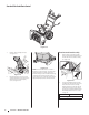
Safe Operation Practices • Set-Up • Operation • Service • Troubleshooting Operator’s Manual Snow Thrower 2-Stage and 3-Stage (300, 500, 600 & 800 Series) Table of Contents Safe Operation Practices......................................... 2 Product Care........................................................... 23 Assembly & Set-Up................................................... 5 Parts/Warranty............... See Separate Supplement Controls & Operation..............................................
1 Important Safe Operation Practices WARNING! This symbol points out important safety instructions which, if not followed, could endanger the personal safety and/or property of yourself and others. Read and follow all instructions in this manual before attempting to operate the equipment. Failure to comply with these instructions may result in personal injury. When you see this symbol.
8. Exercise extreme caution when operating on or crossing gravel surfaces. Stay alert for hidden hazards or traffic. 9. Exercise caution when changing direction and while operating on slopes. Do not operate on steep slopes. 10. Plan your snow-throwing pattern to avoid discharge towards windows, walls, cars etc. Thus, avoiding possible property damage or personal injury caused by a ricochet. 11. Never direct discharge at children, bystanders and pets or allow anyone in front of the machine. 12.
Safety Symbols This page depicts and describes safety symbols that may appear on this product. Read, understand, and follow all instructions on the machine before attempting to assemble and operate. Symbol Description READ THE OPERATOR’S MANUAL(S) Read, understand, and follow all instructions in the manual(s) before attempting to assemble and operate. WARNING— ROTATING BLADES Keep hands out of inlet and discharge openings while machine is running. There are rotating blades inside.
2 Assembly & Set-Up Thank You Thank you for purchasing this product. It was carefully engineered to provide excellent performance when properly operated and maintained. Please read this entire manual prior to operating the equipment. It instructs you how to safely and easily set up, operate and maintain your machine. Please be sure that you, and any other persons who will operate the machine, carefully follow the recommended safety practices at all times.
Tools Required 3. Place shift lever in Forward-6 position or fastest forward speed (if equipped). • Adjustable Wrench or Socket Set 4. • Needle Nose Pliers Observe lower rear area of equipment to be sure both cables (if equipped) are aligned and seated properly in roller guides. See Figure 2-4. Handle Assembly Attach the two carriage screws (b) and nuts (a) removed in Step 2. Finish securing the handle by tightening the top two nuts (c) loosened in Step 2.
E-Z Chute 1. Remove cable tie (if present) securing upper handle to lower handle for shipping purposes. Remove all protective plastic wrapping from handles. NOTE: Be careful NOT to remove the two loosely fitted cable ties that will be utilized later to secure cables. 2. Remove the wing knob (a), saddle washer (b), handle tab (c) and carriage screw (d) on each side of the lower handle. See Figure 2-8.
Standard Side Crank Chute Control Figure 2-12 1. Chute Directional Control Assembly Position chute assembly over base. See Figure 2-13. 1. (a) Figure 2-14 Figure 2-13 2. Close flange keepers to secure chute assembly to chute base. Flange keepers will click into place when properly secure. See Figure 2-14. Remove plastic cap (if present), flat washer (a) and hairpin clip (b) from end of chute directional control assembly. See Figure 2-15.
U-Joint Side Crank Chute Control Figure 2-16 1. NOTE: Ensure the lower chute is secured to the flange on the chute base. The lower edge of the chute keeper should be positioned below the flange on the chute base after being clicked into place. If flange keepers will not easily click into place, use palm of your hand to apply swift, firm pressure to the back of each. Position chute assembly over base. See Figure 2-17. Chute Directional Control Assembly 1. 2.
Overhead Chute Control (w/ Chute Control Rod) 4. Insert chute control rod into the support bracket on rear of the dash panel. See Figure 2-24. 5. Remove hairpin clip (a) from rear of chute control head. See Figure 2-25. Figure 2-24 (a) (b) Figure 2-20 1. Remove wing nut (a) and hex screw (b) from chute control head and clevis pin (c) and cotter pin (d) from chute support bracket. Position chute assembly (forward-facing) over chute base. See Figure 2-21.
2-Way & 4-Way Chute Control NOTE: Chute will not rotate without squeezing trigger on joystick. 5. Rotate joystick to one o’clock position so that indicator arrow on pinion gear below control panel faces upward. See Figure 2-31. 6. Insert chute control rod into pinion gear below joystick. Make sure to line up hole in rod with arrow on pinion gear. See Figure 2-32. Figure 2-31 Figure 2-26 1.
7. Push chute control rod toward control panel until hole in rod lines up with hole in chute control input closest to chute control head and insert hairpin clip (a) removed in Step 1. See Figure 2-33. Overhead Chute Control (w/ Flex Shaft & Steel Chute) (a) Figure 2-33 NOTE: Second hole is used to achieve further engagement of chute control rod into pinion gear if required. Refer to Service section for Chute Control Rod adjustments. 8.
5. Insert flex shaft (b) removed during Handle Assembly from lower handle into rear of chute directional control head. See Figure 2-37. Secure flex shaft to chute control head with hairpin clip (a) removed in Step 4. 6. Insert hex end of flex shaft into chute control rod coupling under dash panel. See Figure 2-38. 7. Ensure speed selector is in fastest forward speed. 8. Remove cotter pin (a) and washer (b) from ferrule on end of shift rod. See Figure 2-39 inset.
5. Insert other end of chute control rod into coupler below handle panel. Make sure to line up flat end of rod and flat end of coupler. You may need to rotate rod around until these two surfaces line up. See Figure 2-46 inset. 6. Push chute control rod toward the control panel until hole in rod lines up with middle hole in chute control input and insert cotter pin (a) removed in Step 1. See Figure 2-47. E-Z Chute Control™ Figure 2-46 (a) Figure 2-48 The E-Z Chute™ does not require any installation.
Shear Pins Storage (If Equipped) Drift Cutters (If Equipped) Tire Pressure (If Applicable) On select units, holes are provided in the rear of the handle panel for shear pin (a) and bow-tie cotter pin (b) storage as shown in Figure 2-50. If not provided, make sure to store them in a safe place until needed. The drift cutters are mounted inverted at the factory for shipping purposes. NOTE: Not applicable to those units equipped with airless tires. Standard 1.
NOTE: If you choose to operate unit on a gravel surface, keep skid shoes in position for maximum clearance between ground and shave plate. 4. Adjust the shave plate to one of 2 mounting positions. Reinstall and tighten the carriage bolts (b) and hex nuts (c) all bolts securely. See Figure 2-56. 5. Adjust the skid shoes. See Skid Shoes on page 15. To adjust skid shoes: 1. Loosen four hex nuts (a) (two on each side) and carriage bolts (b). Move skid shoes to desired position. See Figure 2-55. 8.
Shift Rod (If Equipped) If full range of speeds (forward and reverse) cannot be achieved, adjust shift rod as follows: 1. Place shift lever in fastest forward speed position. 2. Remove cotter pin (a) and washer (b) from adjustment ferrule on shift rod and pull it out from shift lever. See Figure 2-60. (a) (b) Drive Control (Models with out Hydro Transmission) (If Equipped) Drive Control (Models with Hydro Transmission) (If Equipped) NOTE: Drive control on units with E-Z Chute™ is non-adjustable.
3 Controls & Operation Auger Control Lever † † If Equipped Drive Control Lever † Shift Lever † LED Light Bar † Chute Assembly U-Joint Chute Directional Control † Clean Out Tool Drift Cutters † Standard Chute Directional Control † Auger Housing Skid Shoe Augers Overhead Chute Directional Control † Shift Lever Heated Grips † 4-Way/2-Way Chute Directional Control Joystick † Heated Grip Switch † Headlight † Flex Shaft Chute Directional Control † Overhead Chute Directional Control † Shift Rod Hea
Snow thrower controls and features are described below and illustrated in Figure 3-1. NOTE: This Operator’s Manual covers several models. Snow thrower features may vary by model. Not all features in this manual are applicable to all snow thrower models and the snow thrower depicted may differ from yours. NOTE: All references to the left or right side of the snow thrower are from the operator’s position. Any exceptions will be noted.
Drive Control Lever/Auger Clutch Lock* (If Equipped) Steering Trigger Controls (If Equipped) 2-Way Chute Directional Control Joystick (If Equipped) The drive control lever is located on the right handle. Squeeze the control lever against the handle to engage the wheel drive. Release to stop. See Figure 3-5. The left and right wheel steering trigger controls are located on the underside of the handles. Refer to Figure 3-6.
Electric Chute Directional Control Joystick (If Equipped) The electric chute directional control joystick is located on the right side of the dash panel. Refer to Figure 3-10. • To change the direction in which snow is thrown, move the joystick to the right or to the left. • To change the angle/distance which snow is thrown, pivot the joystick forward or backward.
Starting and Stopping the Engine WARNING! To Steer (If Equipped) With the drive control lever engaged, squeeze the right steering trigger control to turn right. Squeeze the left steering trigger control to turn left. Always keep hands and feet clear of moving parts. Do not use a pressurized starting fluid. Vapors are flammable. Refer to the Engine Operator’s Manual for instructions on starting and stopping the engine.
4 Product Care WARNING! Before servicing, repairing or inspecting the snow thrower, disengage the auger control lever. Stop the engine and remove the safety key to prevent unintended starting. Troubleshooting Engine Overheats 1. 1. 4. • • 7. • Replace friction wheel. Refer to Service section on page 27. 1. Extension cord not connected when using electric start button. Chute assembly clogged.
Lubrication To remove skid shoes (Deluxe shown): 1. Remove four carriage bolts (a) and hex flange nuts (b) and flat washers (c) which secure them to the unit. 2. Rotate and reassemble new skid shoes with four carriage bolts (a) (two on each side) and hex flange nuts (b) and flat washers (c). Refer to Figure 4-1. Wheels (a) (a) At least once a season, remove both wheels. Clean and coat axles with a multipurpose automotive grease before reinstalling wheels.
Auger Shaft At least once a season, remove shear pins (a) and cotter pins (b) from auger shaft(s). Spray lubricant inside shaft and around spacers and flange bearings found at either end of shaft(s). See Figure 4-6. Standard U-Joint (a) (a) (a) (a) Figure 4-9 (a) 2. (b) Figure 4-7 (a) 2. (b) NOTE: Three Stage Augers Shown (b) Figure 4-6 IMPORTANT: On 3-stage units, there is an additional shear pin in the rear accelerator. Adjustments Retighten nuts.
3. Roll auger belt off engine pulley. See Figure 4-12. Auger Belt Replacement (300 Series) 1. Allow the engine to run until it is out of fuel. Do not attempt to pour fuel from the engine. 2. Remove the safety key to prevent accidental starting. 3. Remove the self-tapping screw (a) shown in Figure 4-15, and press the plastic tabs (b) to release the belt cover (c). Pull the belt cover (c) up and out from around the engine and chute assembly. Set it aside and save. 4.
5. Place the new drive belt (a) on the engine pulley. See Figure 4-19. 6. Tilt the transmission (b) forward and position the drive belt (c) onto the transmission pulley (d). See Figure 4-18. 7. Reconnect the spring (a) to the bolt on the engine frame and secure the transmission. Reinstall the flange lock nut. See Figure 4-18. 8. Reinstall the auger belt as instructed on page 26. 9. Reassemble the belt cover on the snow thrower 10. Reassemble the belt keeper to the housing.
Notes 28
Medidas de seguridad • Configuración • Funcionamiento • Servicio • Solución de problemas Manual del Operador Máquina quitanieves 2 etapas y 3 etapas (Serie 300, 500, 600 y 800) Índice Medidas de seguridad............................................. 2 Cuidado del producto............................................ 23 Montaje y configuración......................................... 5 Piezas/Garantía...... Consulte el suplemento que se Controles y funcionamiento..................................
1 Importantes medidas de seguridad ¡ADVERTENCIA! La presencia de este símbolo indica que se trata de instrucciones de seguridad importantes que debe respetar para evitar poner en riesgo su seguridad personal y/o material y la de los demás. Lea y siga todas las instrucciones de este manual antes de poner en funcionamiento este equipo. Si no respeta estas instrucciones puede provocar lesiones personales. Cuando vea este símbolo. TENGA EN CUENTA LA ADVERTENCIA.
6. No utilice la máquina bajo la influencia de alcohol o drogas. 7. El silenciador y el motor se calientan y pueden causar quemaduras. No los toque. Mantenga a los niños alejados. 8. Tenga mucho cuidado si cruza o usa la máquina en superficies con grava. Manténgase atento al tráfico y los riesgos ocultos. 9. Tenga cuidado cuando cambie de dirección o cuando opere la máquina en pendientes. No la utilice en pendientes pronunciadas. 10.
Símbolos de seguridad En esta página se presentan y describen los símbolos de seguridad que pueden aparecer en este producto. Lea, entienda y siga todas las instrucciones incluidas en la máquina antes de intentar armarla y hacerla funcionar. Símbolo Descripción LEA LOS MANUALES DEL OPERADOR Lea, entienda y siga todas las instrucciones incluidas en los manuales antes de intentar armarla y hacerla funcionar.
2 Montaje y configuración Gracias Gracias por comprar este producto. Se ha diseñado cuidadosamente para brindar excelente rendimiento si se opera y mantiene correctamente. Por favor lea todo este manual antes de hacer funcionar el equipo. El manual le indica cómo configurar, operar y mantener la máquina de manera fácil y segura. Por favor asegúrese de que usted, y cualquier otra persona que utilice la máquina, siga atentamente y en todo momento las medidas de seguridad recomendadas.
Herramientas necesarias • Llave ajustable o juego de llaves de vaso • Pinzas de punta de aguja 3. Coloque la palanca de cambios en la posición de avance (F) 6 o en la velocidad más rápida hacia adelante (si viene equipada). 4. Observe la parte posterior inferior de la unidad para corroborar que los cables (si se incluyeran) de la barrena (a) y de la transmisión (b) estén alineados y apoyados correctamente en las guías de rodillos. Consulte la Figura 2-4.
E-Z Chute 1. Extraiga la unión de cable (si la hay) que sujeta la barra de control superior a la barra inferior para el envío. Saque de las barras de control todos los envoltorios plásticos de protección. IMPORTANTE: Para evitar que se dañe el cable, resultará necesario levantar la barra de control superior (b) mientras se desliza este precinto hacia arriba. 4. NOTA: Asegúrese de NO extraer las tres uniones de cable flojas que se utilizarán posteriormente para sujetar los cables. 2.
NOTA: Compruebe que el canal inferior esté sujeto a la brida en la base del canal. El borde inferior de la abrazadera del canal debe ubicarse debajo de la brida en la base del canal después de que encaje en su lugar. Si los fijadores de brida no encajan en su lugar fácilmente, utilice la palma de la mano para aplicar una presión rápida y firme en la parte posterior de cada uno. Control de canal con manivela lateral estándar Conjunto del control direccional del canal 1.
Control de canal con manivela lateral de junta universal Conjunto del control direccional del canal 1. Extraiga el pasador de chaveta del extremo del conjunto del control direccional del canal que no está sujeto. 2. Inserte el conjunto del control direccional del canal que no está sujeto en el perno de ojo en el lado izquierdo del conjunto de la manija. Consulte Figura 2-19. (a) Figura 2-19 3.
Control de canal superior (con varilla de control de canal) 4. Inserte la varilla de control del canal en la ménsula de soporte que está en la parte posterior del tablero de instrumentos. Consulte Figura Figura 2-24. 5. Retire el sujetador de horquilla (a) de la parte posterior del cabezal de control del canal. Consulte Figura 2-25. Figura 2-24 (a) (b) Figura 2-20 1.
Control del canal de dos y cuatro direcciones 4. Apriete el disparador de la palanca de control y gire el canal manualmente para que mire hacia adelante. Los orificios en la entrada del control del canal estarán mirando hacia arriba. Consulte Figura 2-30. Entrada de control del canal Vista superior Palanca de control Figura 2-30 NOTA: El canal no girará sin que se haya apretado el disparador en la palanca de control. 5.
NOTA: El orificio de la varilla de control direccional del canal es una referencia para alinear la varilla con la flecha indicadora del engranaje del piñón y quedará a la vista después de haber insertado la varilla. 7.
5. Inserte el eje flexible (b) que se extrajo de la manija inferior durante el Montaje de la manija, en la parte posterior del cabezal de control direccional del canal. Consulte Figura 2-38. Sujete la varilla de control del canal al conjunto del control del canal con el sujetador de horquilla (a) que extrajo en el Paso 4. 6. Inserte el extremo hexagonal del eje flexible en el acoplamiento de la varilla de control del canal que está debajo del tablero de instrumentos. Consulte Figura 2-38. 7.
5. Inserte el otro extremo de la varilla de control del canal en el acoplador que se encuentra debajo del panel de la manija. Asegúrese de alinear el extremo plano de la varilla y el extremo plano del acoplador. Puede ser necesario girar la varilla hasta que se alineen estas dos superficies. Consulte el recuadro Figura 2-46. E-Z Chute Control™ Figura 2-46 6.
Almacenamiento de los pasadores de cuchilla (si vienen equipados) En determinadas unidades, se incluyen orificios en la parte posterior del panel de la manija para guardar el pasador de cuchilla (a) y el pasador de chaveta con unión curva (b) como se indica en la Figura 2-50. Si no se incluyen, asegúrese de guardarlos en un lugar seguro hasta que sean necesarios.
NOTA: Si tiene que usar la unidad sobre grava, 4. Regule la placa de raspada en una de las 2 posiciones de montaje. Vuelva a instalar y apriete bien los pernos de carro (a) y tuercas hexagonales (c). Consulte la Figura 2-56. Para ajustar las zapatas antideslizantes: 5. Ajuste las zapatas antideslizantes. Consulte las zapatas antideslizantes en la página 15. mantenga las zapatas antideslizantes en la posición que permita lograr una separación máxima entre el piso y la placa de raspado. 1.
Varilla de cambios (si viene equipada) Si no se puede lograr la gama completa de velocidades (marcha adelante y atrás), ajuste la varilla de cambios de la siguiente manera: 1. Coloque la palanca de cambios en la posición más rápida de marcha adelante. 2. Extraiga el pasador de chaveta (a) y la arandela (b) de la férula de ajuste de la varilla de cambios y extráigala de la palanca de cambios. Consulte la Figura 2-57.
3 Controles y funcionamiento † If Equipped Palanca de control de la barrena † Palanca de control de la transmisión † Palanca de control de la transmisión † Barra de luces LED † Conjunto del canal Control direccional del canal de junta universal † Herramienta de limpieza Cortadores de desplazamiento de nieve † Control direccional del canal estándar † Caja de la barrena Zapata antideslizante Barrenas Palanca de cambios Agarres térmicos † Palanca de control direccional del canal de 4/2 direccione
Los controles y las características de la máquina quitanieves se describen a continuación y se ilustran en la Figura 3-1. NOTA: Este manual de operación, corresponde a numerosos modelos. Las características técnicas de la máquina quitanieves pueden variar según los modelos. No todas las características en este manual se aplican a todos los modelos de máquina quitanieves y la máquina que se ilustra aquí puede diferir de la suya.
Palanca de control de la transmisión / Traba del embrague de la barrena* Controles de la dirección (si vienen equipados) La palanca de control de la transmisión está ubicada en la manija derecha. Oprima la palanca de control contra la manija para activar la transmisión de las ruedas. Suéltela para que se detenga. Consulte la Figura 3-5. Los controles de la dirección del volante izquierdo y derecho se ubican en la parte inferior de las manijas. Consulte la Figura 3-6.
Palanca de control direccional del canal eléctrico (si está incluida) La palanca de control direccional del canal eléctrico está ubicada en el lado derecho del tablero de instrumentos. Consulte la Figura 3-10. • • Para cambiar la dirección en que se quita la nieve, mueva la palanca de control hacia la derecha o hacia la izquierda. Para cambiar el ángulo/la distancia en que se quita la nieve, gire la palanca de control hacia adelante o hacia atrás. 2.
Procedimiento para engranar la transmisión Procedimiento de dirección (si viene equipada) 1. Con la palanca de control de la transmisión engranada, presione el control de dirección derecho para girar a la derecha. Presione el control de dirección izquierdo para girar a la izquierda. 2.
4 Cuidado del producto ¡ADVERTENCIA! Antes de realizar tareas de mantenimiento, reparación o inspección en la máquina quitanieves, desengrane la palanca de control de la barrena. Pare el motor y retire la llave de seguridad para evitar el encendido accidental del motor. Solución de problemas El motor recalienta 1. 3. 1. 1. El depósito de combustible está vacío o el combustible se ha echado a perder. La llave de seguridad no está en el interruptor.
Para retirar la placa de raspado: Almacenamiento Fuera de Temporada 1. Deje el motor en marcha hasta que se acabe el combustible. No intente verter combustible del motor. Si no se va a usar la unidad durante 30 días o más, siga las instrucciones de almacenamiento que se incluyen a continuación. 2. Gire con cuidado la unidad hacia arriba y hacia adelante de manera que quede apoyada sobre la caja de la barrena. 1. 3.
Ajustes 2. Varilla de cambios (si viene equipada) Consulte Varilla de cambios en la página 17 para obtener instrucciones sobre el ajuste de la varilla de cambios. Retire la varilla de control del canal hasta que el orificio de la misma quede alineado con el segundo orificio del conjunto de rotación del canal. Consulte la Figura 4-8.
4. Gire con cuidado la unidad hacia arriba y hacia adelante de manera que quede apoyada sobre la caja de la barrena. 5. Saque la cubierta del marco desde debajo de la unidad, para lo que debe extraer los tornillos autorroscantes que la sujetan. Consulte la Figura 4-4. 6. 2. Retire la llave para evitar el encendido accidental. Retire el tornillo autorroscante se muestra en la Figura 4-15, y presione las lengüetas de plástico para liberar la cubierta de la correa.
6. Incline la transmisión hacia adelante y ubique la correa de transmisión en la polea de transmisión. Consulte la Figura 4-18. 7. Vuelva a conectar el resorte al perno en el marco del motor y ajuste la transmisión. Vuelva a instalar la tuerca de seguridad bridada. Consulte la Figura 4-18. 8. Reinstall the auger belt as instructed on page 26. 9. Vuelva a montar la cubierta de la correa en la máquina quitanieve 10. Vuelva a montar el guardacorrea a la caja. 4.
MTD LLC, P.O.