
Full Product Manual


15Section 2 — ASSembly & Set-Up
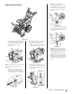
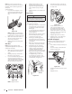
Shear Pins Storage (If Equipped)
On select units, holes are provided in the rear
of the handle panel for shear pin (a) and
bow-tie cotter pin (b) storage as shown in
Figure 2-50. If not provided, make sure to store
them in a safe place until needed.
(a)
(b)
(a)
(b)
(a)
(b)
Figure 2-50
NOTE: Three stage units come with four (4)
shear pins and bow-tie cotter pins.
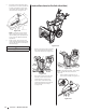
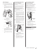
Chute Clean-Out Tool
The chute clean-out tool is fastened to the top
of the auger housing with a mounting clip. See
Figure 2-51.
Figure 2-51
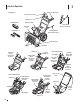
Drift Cutters (If Equipped)
The drift cutters are mounted inverted at the
factory for shipping purposes.
Standard
1. Remove two screws (a) and lock nuts (b)
that secure each drift cutter, and remove
them from the sides of auger housing.
See Figure 2-52.
(a)
(a)
(b)
(b)
Figure 2-52
2. Turn the drift cutters around and
position them as shown in Figure 2-51 to
the outside of the auger housing.
3. Attach drift cutters with screws (a) and
lock nuts (b) removed in Step 1.
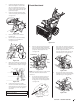
Tool-less
1. Remove two carriage bolts (a) and wing
nuts (b) that secure each drift cutter, and
remove them from the sides of auger
housing. See Figure 2-53.
(b)
(b)
(a)
(a)
Figure 2-53
2. Turn the drift cutters around and
position them as shown in Figure 2-53 to
the outside of the auger housing.
3. Attach drift cutters with carriage bolts
(a) and wing nuts (b) removed in Step 1.
Tire Pressure (If Applicable)
NOTE: Not applicable to those units equipped
with airless tires.
WARNING!
Under any circumstance do not exceed manufacturer’s
recommended psi. Equal tire pressure should be
maintained at all times. Excessive pressure when
seating beads may cause tire/rim assembly to burst
with force sufficient to cause serious injury. Refer to
sidewall of tire for recommended pressure.
The tires are over-inflated for shipping
purposes. Check tire pressure before
operating unit. Refer to tire side wall for tire
manufacturer’s recommended psi and deflate
(or inflate) tires as necessary.
NOTE: Equal tire pressure is to be maintained
at all times for performance purposes.
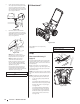
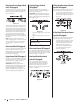
Adjustments
Chute Assembly
NOTE: For models with 2-Way/4-Way or Electric
Chute Directional Control and/or models
with chute-pitch controls see Controls and
Operation on page 20-21.
On units with manual chute tilt, including E-Z
Chute™, the distance snow is thrown can be
adjusted by changing angle of chute assembly.
To do so:
1. Loosen wing knob found on left side of
chute assembly. See Figure 2-54.
Figure 2-54
2. Pivot chute upward or downward before
retightening wing knob.
Skid Shoes
The snow thrower skid shoes are adjusted at
the factory set roughly 1/8” below the shave
plate. Adjust them downward, if desired, prior
to operating the snow thrower.
CAUTION
Use extreme caution when on gravel and adjust auger
housing height to clear gravel or crushed rock surfaces to
avoid picking up and throwing gravel or crushed rock.
• For close snow removal on a smooth
surface, raise skid shoes higher on auger
housing.
• Use a lower position when area to be
cleared is uneven, such as a gravel
driveway.