Safe Operation Practices • Set-Up • Operation • Maintenance • Service • Troubleshooting • Warranty Operator’s Manual Track Drive Snow Thrower — Storm Tracker 2690XP WARNING READ AND FOLLOW ALL SAFETY RULES AND INSTRUCTIONS IN THIS MANUAL BEFORE ATTEMPTING TO OPERATE THIS MACHINE. FAILURE TO COMPLY WITH THESE INSTRUCTIONS MAY RESULT IN PERSONAL INJURY. TROY-BILT LLC, P.O. BOX 361131 CLEVELAND, OHIO 44136-0019 Printed In USA Form No.
1 To The Owner Thank You Thank you for purchasing a Troy-Bilt Snow Thrower. It was carefully engineered to provide excellent performance when properly operated and maintained. Please read this entire manual prior to operating the equipment. It instructs you how to safely and easily set up, operate and maintain your machine. Please be sure that you, and any other persons who will operate the machine, carefully follow the recommended safety practices at all times.
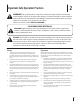
Important Safe Operation Practices 2 WARNING! This symbol points out important safety instructions which, if not followed, could endanger the personal safety and/or property of yourself and others. Read and follow all instructions in this manual before attempting to operate this machine. Failure to comply with these instructions may result in personal injury. When you see this symbol.
Safe Handling of Gasoline 5. To avoid personal injury or property damage use extreme care in handling gasoline. Gasoline is extremely flammable and the vapors are explosive. Serious personal injury can occur when gasoline is spilled on yourself or your clothes which can ignite. Wash your skin and change clothes immediately. Never run an engine indoors or in a poorly ventilated area. Engine exhaust contains carbon monoxide, an odorless and deadly gas. 6.
Clearing a Clogged Discharge Chute Hand contact with the rotating impeller inside the discharge chute is the most common cause of injury associated with snow throwers. Never use your hand to clean out the discharge chute. To clear the chute: 1. SHUT THE ENGINE OFF! 2. Wait 10 seconds to be sure the impeller blades have stopped rotating. 3. Always use a clean-out tool, not your hands. Maintenance & Storage 1. Never tamper with safety devices. Check their proper operation regularly.
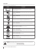
Safety Symbols This page depicts and describes safety symbols that may appear on this product. Read, understand, and follow all instructions on the machine before attempting to assemble and operate. Symbol Description READ THE OPERATOR’S MANUAL(S) Read, understand, and follow all instructions in the manual(s) before attempting to assemble and operate WARNING— ROTATING BLADES Keep hands out of inlet and discharge openings while machine is running.
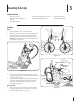
3 Assembly & Set-Up Contents of Crate • One Snow Thrower • Two Replacement Auger Shear Pins • One Chute Assembly • One Snow Thrower Operator’s Manual • One Product Registration Card • One Chute Control Rod • One Engine Manual Assembly Handle 1. Place the shift lever in the Forward-6 position. 2. Remove the lower plastic wing nut and carriage bolt from each side of the upper handle; raise the upper handle assembly until it snaps over the lower handle. See Fig. 3-1.
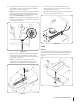
2. Insert chute control rod into chute control head. Push rod as far into chute control head as possible, keeping the holes in the rod pointing upward. See Fig. 3-4. 4. Squeeze the trigger on the joystick and rotate the chute by hand to face forward. The holes in the chute control input will be facing up. See Fig. 3-6. NOTE: The chute will not rotate without squeezing the trigger on the joystick. Chute Control Input Top View Figure 3-4 3.
6. Insert the chute control rod into the pinion gear below the joystick. Make sure to line up the hole in the rod with the arrow on the pinion gear. See Fig. 3-8. 8. Finish securing chute control head to chute support bracket with wing nut, clevis pin, and bow-tie cotter pin removed in step 1. See Fig. 3-3. NOTE: The chute control rod will fit snuggly into the pinion gear.
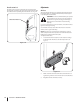
Chute Clean-Out Tool Adjustments The chute clean-out tool is fastened to the top of the auger housing with a mounting clip and a cable tie at the factory. Cut the cable tie before operating the snow thrower. See Fig. 3-12. Skid Shoes The snow thrower skid shoes are adjusted upward at the factory for shipping purposes. Adjust them downward, if desired, prior to operating the snow thrower.
Auger Control Warning! Prior to operating your snow thrower, carefully read and follow all the instructions below. Perform all adjustments to verify your snow thrower is operating safely and properly. Check the adjustment of the auger control as follows: 1. When the auger control is released and in the disengaged “up” position, the cable should have very little slack. It should NOT be tight. 2. In a well-ventilated area, start the snow thrower engine. Refer to your Engine Operator’s Manual. 3.
4 Controls and Features Track Lock Lever Chute Directional Control Drive Control Shift Lever Auger Control Heated Grips Headlight Steering Trigger Control Chute Assembly Chute Clean Out Tool Skid Shoe Augers Figure 4-1 WARNING! Read, understand, and follow all instructions and warnings on the machine and in this manual before operating. Shift Lever The shift lever is located on the right side of the handle panel and is used to determine both the ground speed and direction of travel.
Skid Shoe Chute Assembly The space between the shave plate and the ground can be adjusted by positioning the skid shoes. Refer to Skid Shoe Adjustment on page 10. Snow drawn into the auger housing is discharged out the chute assembly. Track Drive Control / Auger Clutch Lock The track drive control is located on the right handle. Squeeze the control grip against the handle to engage the track drive. Release to stop. NOTE: Always release the drive control before changing speeds.
Track Lock Lever The track lock lever is located on the right side of the snow thrower and is used to select the position of the auger housing and the method of track operation. Move the lever to the right, then forward or backward to one of the three positions. Transport Raises the front end of the snow thrower for easy transport. Using proper caution, this position may also be used on many gravel driveways to clear snow while leaving gravel undisturbed.
5 Operation Starting and Stopping the Engine Set Track Position Refer to the Engine Operator’s Manual packed with your snow thrower for instructions on starting and stopping the engine. Move the track lock lever to the right, then forward or backward to one of the three positions. See Fig. 5-2.
6 Maintenance & Adjustments Maintenance 2. Engine Remove the frame cover from the underside of the snow thrower by removing the self-tapping screws which secure it. Refer to Fig 6-2. Refer to the Engine Operator’s Manual. Shave Plate and Skid Shoes The shave plate and skid shoes on the bottom of the snow thrower are subject to wear. They should be checked periodically and replaced when necessary. NOTE: Deluxe skid shoes have two wear edges.
Auger Shaft Auger Control At least once a season, remove the shear pins from the auger shaft. Spray lubricant inside the shaft and around the spacers and the flange bearings found at either end of the shaft. See Fig. 6-4. Refer to the Assembly and Set-up section for instructions on adjusting the auger control cable. Skid Shoes Refer to the Assembly and Set-up section for instructions on adjusting the skid shoes. Shear Pin Track Tension Over time the track can stretch.
Drive Control Chute Directional Control When the drive control is released and in the disengaged “up” position, the cable should have very little slack. It should NOT be tight. To adjust the chute control rod, proceed as follows: 1. Remove the cotter pin from the hole closest to the chute assembly on the chute rotation assembly. NOTE: If excessive slack is present in the drive cable or if the snow thrower’s drive is disengaging intermittently during operation, the cable may be in need of adjustment.
7 Service Belt Replacement 4. Auger Belt Remove the frame cover from the underside of the snow thrower by removing the self-tapping screws which secure it. See Fig. 7-2. NOTE: It is not necessary to remove both belts in order to change either one. If changing just one belt, be certain to check the condition of the other belt. 1. Allow the engine to run until it is out of fuel. Do not attempt to pour fuel from the engine. Remove the key to avoid unintended starting. 2.
6. Unhook the idler spring from the hex bolt on the auger housing. See Fig. 7-4. Drive Belt To remove and replace your snow thrower’s drive belt, proceed as follows: 1. To prevent spillage, remove all fuel from tank by running engine until it stops. Do not attempt to pour fuel from the engine. 2. Remove the plastic belt cover on the front of the engine by removing the two self-tapping screws. Ref. Fig. 7-1. 3. Carefully pivot the snow thrower up and forward so that it rests on the auger housing. 4.
7. Slip the drive belt off the pulley and between friction wheel and drive pulley. See Fig. 7-7. Sprocket Friction Wheel Removal The rubber on the friction wheel is subject to wear and should be checked after 25 hours of operation, and periodically thereafter. Replace the friction wheel rubber if any signs of wear or cracking are found. 1. Allow the engine to run until it is out of fuel. Do not attempt to pour fuel from the engine. 2.
6. If replacing the entire assembly, put the new friction wheel assembly in place and follow the steps in reverse to reassemble. Repeat the drive control test on page 18. If you only want to replace the friction wheel rubber, continue with step 7. NOTE: Make sure the shift lever pin is in place in the bearing housing. See Fig. 7-9 inset. 10. NOTE: Make sure to install the gear shaft through the sprocket shown in Fig. 7-7.
8 Troubleshooting Problem Engine fails to start Cause Remedy 1. Fuel tank empty, or stale fuel. 1. Fill tank with clean, fresh gasoline. Fuel becomes stale after thirty days. 2. Blocked fuel line. 2. Clean the fuel line. 3. Choke not in the RUN position. 3. Move choke control to RUN position 4. Faulty spark plug. 4. Clean, adjust gap or replace. 5. Key not in ignition switch on engine. 5. Insert the key fully into the switch. 6. Spark plug wire disconnected. 6. Connect spark plug wire. 7.
9 Replacement Parts Component Part Number and Description 929-0071A Extension Cord, 110V 954-04050 954-04260 Auger Drive Belt Wheel Drive Belt 684-04159 935-04054 Friction Wheel Assembly Friction Wheel Rubber 725-1629 Lamp, 12 Volt 738-04124A 714-04040 Shear Pin, 1.
10 Attachments & Accessories The following attachments and accessories are available for your Troy-Bilt snow thrower. Phone (800) 828-5500 for information regarding compatibility, price and availability (have your full model number and serial number ready).
MANUFACTURER’S LIMITED WARRANTY FOR The limited warranty set forth below is given by Troy-Bilt LLC with respect to new merchandise purchased and used in the United States and/or its territories and possessions, and by MTD Products Limited with respect to new merchandise purchased and used in Canada and/ or its territories and possessions (either entity respectively, “TroyBilt”). c. Service completed by someone other than an authorized service dealer.
Medidas importantes de seguridad • Configuración • Funcionamiento • Mantenimiento • Servicio • Solución de problemas • Garantía Manual del operador Máquina quitanieve de dos etapas — Storm Tracker 2690XP ADVERTENCIA LEA Y SIGA TODAS LAS INSTRUCCIONES DE ESTE MANUAL ANTES DE PONER EN FUNCIONAMIENTO ESTA MÁQUINA. SI NO RESPETA ESTAS INSTRUCCIONES PUEDE PROVOCAR LESIONES PERSONALES. TROY-BILT LLC, P.O. BOX 361131 CLEVELAND, OHIO 44136-0019 Impreso en Estados Unidos de América Formulario No.
1 Al propietario Gracias Gracias por comprar una Troy-Bilt máquina quitanieve. La misma ha sido diseñada cuidadosamente para brindar excelente rendimiento si se la opera y mantiene correctamente. Por favor lea todo este manual antes de operar el equipo. Le indica cómo configurar, operar y mantener la máquina con seguridad y fácilmente. Por favor asegúrese de seguir cuidadosamente y en todo momento las prácticas de seguridad recomendadas, y hacérselas seguir a cualquier otra persona que opere la máquina.
2 Medidas importantes de seguridad ¡ADVERTENCIA! La presencia de este símbolo indica que se trata de instrucciones importantes de seguridad que se deben respetar para evitar poner en peligro su seguridad personal y/o material y la de otras personas. Lea y siga todas las instrucciones de este manual antes de poner en funcionamiento esta máquina. Si no respeta estas instrucciones puede provocar lesiones personales. Cuando vea este símbolo.
6. Nunca intente realizar ajustes mientras el motor está en marcha excepto en los casos específicamente recomendados en el manual del operador. 7. Deje que el motor y la máquina se adapten a la temperatura exterior antes de comenzar a sacar la nieve. Manejo seguro de la gasolina Para evitar lesiones personales o daños materiales tenga mucho cuidado cuando trabaje con gasolina. La gasolina es sumamente inflamable y sus vapores pueden causar explosiones.
20. 21. Para encender el motor, jale de la cuerda lentamente hasta que sienta resistencia, luego jale rápidamente. El repliegue rápido de la cuerda de arranque (tensión de retroceso) le jalará la mano y el brazo hacia el motor más rápido de lo que usted puede soltar. El resultado pueden ser huesos rotos, fracturas, hematomas o esguinces. Si se presentan situaciones que no están previstas en este manual, sea cuidadoso y use el sentido común.
Símbolos de Seguridad Esta página describe los símbolos y figuras de seguridad internacionales que pueden aparecer en este producto. Lea el manual del operador para obtener la información terminada sobre seguridad, reunirse, operación y mantenimiento y reparación. Símbolo Descripción LEA EL MANUAL DEL OPERADOR (S) Lea, entienda, y siga todas las instrucciones en el manual (es) antes de intentar reunirse y funcionar.
3 Montaje y Configuración Contenido de la caja • Una máquina quitanieve • Dos pasadores de cuchilla de barrena de repuesto • Canal de montaje • Un Manual del Operador de la Máquina Quitanieve • Varilla hexagonal • Un Manual del Motor Montaje Manija 1. Coloque la palanca de cambios en la posición de avance (F) 6. 2.
2. Insertar varilla hexagonal en la tolva de control de la cabeza. Varilla de empuje en la medida de control de la tolva en la cabeza como sea posible, manteniendo los orificios de la varilla hexagonal apuntando hacia arriba. Vea la Fig. 3-4. 4. Aprieta el gatillo en el mando y girar la tolva de la mano a la cara hacia adelante. Los orificios de la tolva de entrada de control será hacia arriba. Vea la Fig. 3-6. Nota: La tolva de no rotar sin apretar el gatillo sobre el joystick.
6. Insertar la varilla hexagonal en la marcha por debajo de piñón el joystick. Asegúrese de alinear el agujero de la varilla hexagonal con la flecha en el piñón artes. Vea la Fig. 3-8. Nota: El agujero es una referencia para la armonización de la vara con el indicador de flecha en el piñón artes. 8. Finalizar asegurar el control de la cabeza a la tolva tolva de soporte con tuerca de mariposa, horquilla alfiler, y arco-tie Cotter pines eliminado en el paso 1. Vea la Fig. 3-3. 9.
Herramienta de limpieza del canal Ajustes La herramienta de limpieza del canal viene de fábrica ajustada a la parte superior de la caja de la barrena con un pasador de ensamblado y una unión de cable. Corte la unión de cable antes de operar la máquina quitanieve. Vea la Fig. 3-12. Zapatas antideslizantes Las zapatas antideslizantes de la máquina quitanieve se ajustan para arriba en fábrica para el envío. Si lo desea, puede ajustarlas hacia abajo antes de hacer funcionar la máquina quitanieve.
Control de la barrena 8. ¡Advertencia! Antes de operar su máquina quitanieve, lea atentamente y cumpla todas las instrucciones que aparecen a continuación. Realice todos los ajustes para verificar que la máquina está operando con seguridad y correctamente. Hilo de la virola sin convertir el cable a la “Z” montaje hasta que no haya holgura en el cable. Ver fig. 3-14. No en exceso el cable. Mantenga los pisos en la virola con unos alicates y apriete la tuerca contra el atasco de la virola.
4 Controles y Características Palanca de traba de las orugas Control direccional del canal Control de Transmisión Control de la barrena Palanca de cambios Agarre térmico Faro delantero Controles de dirección de las orugas Montaje del canal Herramienta de limpieza del canal Zapatas Antideslizantes Barrenas Figura 4-1 ¡ADVERTENCIA! Lea, comprenda y siga todas las instrucciones y advertencias que aparecen en la máquina y en este manual antes de hacerla funcionar.
Para desactivar los puños calefactables, mueva el interruptor que se encuentran en la parte trasera del panel de instrumentos en la posición OFF. Zapata antideslizante Se puede regular el espacio que existe entre la placa de raspado y el suelo colocando las zapatas antideslizantes. Consulte Ajuste de las zapatas antideslizantes en la página 10. Control de transmisión de orugas / Traba del embrague de la barrena El control de transmisión de orugas está ubicado en la manija derecha.
Palanca de traba de las orugas La palanca de traba de la oruga está situada en el lado derecho de la máquina quitanieve, y se usa para seleccionar la posición de la caja de la barrena y el método de operación de la oruga. Mueva la palanca a la derecha, y luego hacia delante o hacia atrás, a una de las tres posiciones. Transporte eleva el extremo frontal de la máquina quitanieve para facilitar el transporte.
5 Funcionamiento Encendido del Motor y Detención del Motor Palanca de traba de las orugas Consulte el Mantenimiento del Motor para motores embalado con la máquina para ver el Encendido del Motor y Detención del motor. Mueva la palanca a la derecha, y luego hacia delante o hacia atrás, a una de las tres posiciones. Vea Fig. 5-2. Procedimiento para engranar la transmisión 1. 2.
6 Mantenimiento y Ajustes Mantenimiento 1. Haga funcionar hasta vaciar el tanque de combustible, luego gire con cuidado la máquina quitanieve hacia arriba y hacia adelante para que quede apoyada sobre la caja de la barrena. 2. Saque la cubierta del marco desde debajo de la máquina quitanieve retirando los cuatro tornillos autorroscantes que la sujetan. Consulte la Fig. 6-2. Motor Consulte el manual del motor.
Eje de la barrena Control de la barrena Al menos una vez por temporada, quite los pasadores de cuchilla del eje de la barrena. Rocíe lubricante en el interior del eje y alrededor de los separadores y los cojinetes bridados que se encuentran en ambos extremos del eje. Vea la Fig. 6-4. Consulte la sección Montaje y Configuración para ver las instrucciones de ajuste del cable de control de la barrena.
Control de la transmisión Control direccional del canal Cuando se suelta el control de la transmisión y está en posición desenganchada arriba, el cable debe tener muy poco juego. NO debe estar tenso. Para ajustar la varilla de control del canal proceda de la siguiente manera: NOTA: Si el cable de transmisión tiene demasiado juego o si la transmisión de la máquina quitanieve se desengancha intermitentemente durante la operación, es posible que deba ajustar el cable. 1.
7 Servicio Cambio de correa 4. Correa de barrena Saque la cubierta del marco desde debajo de la máquina quitanieve retirando los tornillos autorroscantes que la sujetan. Vea la Fig. 7-2. NOTA: No hace falta sacar ambas correas para cambiar una de ellas. Si cambia una sola correa, no olvide verificar el estado de la otra. 1. Drene la gasolina de la máquina quitanieve o coloque un trozo de película plástica debajo del tapón de combustible. 2.
6. Desenganche el resorte intermedio del perno hexagonal en la caja de la barrena. Vea la Fig. 7-4. Perno de parada Perno hexagonal Correa de la transmisión Para retirar y reemplazar la correa de la barrena de su máquina quitanieve, proceda como se indica a continuación: 1. Drene la gasolina de la máquina tiranieve o haga funcionar hasta vaciar el tanque. 2. Saque la cubierta plástica de la correa ubicada en el frente del motor retirando los dos tornillos autorroscantes. Ref. Fig. 7-1. 3.
7. Quite la correa de transmisión de la polea y de entre la rueda de fricción y la polea de transmisión. Vea la Fig. 7-7. Rueda de espigas Correa de la transmisión Extracción de la rueda de fricción La goma de la rueda de fricción está sujeta a desgaste y se la debe controlar después de las primeras 25 horas de funcionamiento y luego de forma periódica. Reemplace la goma de la rueda de fricción si detecta signos de desgaste o grietas. 1. Drene la gasolina de la máquina quitanieve. 2.
6. 7. Si está reemplazando todo el montaje, coloque el nuevo montaje de la rueda de fricción en su lugar y siga las instrucciones a la inversa para volver a armar. Si solo desea reemplazar la goma de la rueda de fricción, continúe con el paso 7. Saque los cuatro tornillos del montaje de la rueda de fricción. Vea la Fig. 7-10. Tornillos Reemplazo de los Pasadores de Cuchilla Las barrenas están ajustadas al eje espiral con dos pasadores de cuchilla y pasadores de chaveta.
8 Solución de Problemas Problema Causa Solución 1. El control del cebador no está en la posición CHOKE (encendido). 1. Ponga el control del cebador en la posición CHOKE (encendido). 2. Se ha desconectado el cable de la bujía. 2. Conecte el cable a la bujía. 3. El depósito de combustible está vacío o el combustible se ha echado a perder. 3. Llene el tanque con gasolina limpia y fresca. 4. El motor no está cebado. 4. Cebe el motor tal como se explicó en la sección Funcionamiento. 5.
9 Piezas de Reemplazo Componente Número de pieza y Descripción 929-0071A Cordón prolongador, 110V 954-04050 954-04260 Correa de transmisión de la barrena Correa de transmisión de la rueda 684-04159 935-04054 Montaje de rueda de fricción Goma de la rueda de fricción 725-1629 Lámpara, 12,5V, 27,5W 738-04124A 714-04040 Pasador de cuchilla, 1,50 Pasador de chaveta con unión curva 790-00091 Zapata antideslizante, Deluxe 931-2643 Herramienta de limpieza del canal 790-00121 Placa de raspado, 26”
10 Aditamentos y Accesorios Los siguientes aditamentos y accesorios son compatibles con el máquina quitanieve. Llame (800) 828-5500 para la información con respecto a la compatibilidad, el precio y la disponibilidad (tener su número de modelo completo y número de serie).
GARANTÍA LIMITADA DEL FABRICANTE PARA La siguiente garantía limitada es otorgada por Troy-Bilt LLC con respecto a nuevos productos adquiridos y utilizados en Estados Unidos y/o sus territorios y posesiones, y por MTD Products Limited con respecto a nuevos productos adquiridos y utilizados en Canadá y/o sus territorios y posesiones (cualquiera de las dos entidades, respectivamente, “Troy-Bilt”).