
Full Product Manual


17
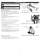
Fig. 23
Fig. 24
Locking Rod
Output Shaft Hole
Locking Rod
Output Shaft
Locking Rod Slot
Lower Shaft
Housing
REPLACING THE EDGER BLADE
Removing the Edger Blade
1. Align the output shaft hole with the locking rod slot. Insert the
lock ing rod through the locking rod slot and into the output shaft
hole (Fig. 23).
2. Keep the locking rod in place by holding it next to the lower
shaft housing (Fig. 24).
3. While hold ing the lock ing rod, loosen the lock nut by turning it
clock wise with a 13 mm wrench (Fig. 25).
4. Remove the locking rod. Remove the lock nut, blade retainer
and edger blade (Fig. 26). Keep the lock nut and blade retainer
for installing the new edger blade.
Installing the Edger Blade
1. Lower the new edger blade onto the output shaft bushing (Fig. 26).
Make sure the blade is flat against the output shaft bushing.
2. Place the blade retainer onto the output shaft with the flat
surface against the blade (Fig. 26).
3. Screw the nut onto the output shaft (Fig. 26).
4. Align the output shaft hole with the locking rod slot. Insert the
lock ing rod through the locking rod slot and into the output shaft
hole (Fig. 23).
5. Keep the locking rod in place by holding it next to the shaft
housing (Fig. 24).
6. While holding the locking rod, tighten the lock nut by turning it
counterclockwise (Fig. 25). Make sure that the edger blade
stays flat and centered against the output shaft while tightening
the lock nut.
If you have a torque wrench, tighten the lock nut to 325-335
in.•lbs (37-38 N•m).
If you do not have a torque wrench, tighten the lock nut with a 13
mm wrench, until the lock nut presses against the blade retainer
and the edger blade is snug. Make sure the edger blade is
installed correctly, then rotate the nut an additional 1/4-1/2 turn.
7. Remove the locking rod.
WARNING:
Make sure the blade is flat against the
output shaft bushing after the lock nut is tightened. If the
blade is off-cen ter, the unit will be dam aged by vibration,
and the blade may fly off, which can cause serious
personal in ju ry.
WARNING:
To avoid serious personal injury or damage
to the unit, do not start or operate the unit with the locking
rod inserted into the locking rod slot.
Fig. 25
Tighten
Fig. 26
Edger Blade
Loosen
Lock Nut
Blade Retainer
Locking Rod
Lock Nut
Output Shaft
Output Shaft
Bushing