Important Safe Operation Practices • Assembly & Set-Up • Controls & Operation • Product Care Operator’s Manual Riding Mower Table of Contents Important Safe Operation Practices...................... 2 Product Care............................................................15 Assembly & Set-Up................................................... 7 Parts/Warranty............... See Separate Supplement Controls & Operation..............................................
Important Safe Operation Practices 2 WARNING This symbol points out important safety instructions which, if not followed, could endanger the personal safety and/or property of yourself and others. Read and follow all instructions in this manual before attempting to operate this machine. Failure to comply with these instructions may result in personal injury. When you see this symbol.
Do: 1. 2. 3. 4. 5. 6. 7. b. Mow up and down slopes, not across. Exercise extreme caution when changing direction on slopes. Watch for holes, ruts, bumps, rocks, or other hidden objects. Uneven terrain could overturn the machine. Tall grass can hide obstacles. Use slow speed. Choose a low enough speed setting so that you will not have to stop or shift while on the slope. Tires may lose traction on slopes even though the brakes are functioning properly.
5. 6. 7. 8. 9. 10. 11. Check the blade(s) and engine mounting bolts at frequent intervals for proper tightness. Also, visually inspect blade(s) for damage (e.g., excessive wear, bent, cracked). Replace the blade(s) with the original equipment manufacturer’s (O.E.M.) blade(s) only, listed in this manual. “Use of parts which do not meet the original equipment specifications may lead to improper performance and compromise safety!” Mower blades are sharp.
Symbol Description DANGER— BYSTANDERS Keep bystanders, helpers, children and pets at least 75 feet from the machine while it is in operation. WARNING— THROWN OBJECTS This machine may pick up and throw and objects which can cause serious personal injury. WARNING—THROWN OBJECTS This machine may pick up and throw and objects which can cause serious personal injury. WARNING— SLOPE OPERATION Go up and down slopes, not across. WARNING— SLOPE OPERATION Use extra caution on slopes.
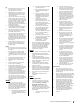
Section 2 — Important Safe Operation Practices Figure 1 12°/21% Slope Do not operate machine on slopes in excess of 15 degrees. All slopes require extra caution. If you cannot back up the slope or if you feel uneasy on it, do not mow it. Always mow up and down slopes, never across the face of slopes. WARNING! Slopes are a major factor related to tip-over and roll-over accidents which can result in severe injury or death. To check the slope, proceed as follows: 1.
a) 2 Assembly & Set-Up Thank You Thank you for purchasing this product. It was carefully engineered to provide excellent performance when properly operated and maintained. Please read this entire manual prior to operating the equipment. It instructs you how to safely and easily set up, operate and maintain your machine. Please be sure that you, and any other persons who will operate the machine, carefully follow the recommended safety practices at all times.
6. Lower the steering wheel assembly (a) onto the lower steering shaft (b) and secure with the shoulder bolt (c) and lock nut (d) previously removed. See Figure 2-3. Attaching the Seat 4. If the seat for your riding mower was not attached at the factory, follow the applicable instructions below to attach it. 1. CAUTION Remove the shoulder bolts (a) and lock nuts (b) from the seat mounting bracket (c) included in your hardware pack. See Figure 2-5. (a) Do not use any type of power tool (e.g.
2. Install the deck chute (b) into the deck discharge opening on the deck. The rear of the chute (b) should be under the tab (f) on the rear deck bracket (g). The studs (c) on the deck surface will fit through the holes on the upper portion of the deck chute (b). The small tab (d) on the deck lip area will fit through the square cutout on the lower portion of the deck chute (b). See Figure 2-9. Install the Rear Engine Cover (If equipped) Installing the Bumper (If equipped) 1. 1.
2. Remove the plastic cover (c), if present, from the positive battery terminal (d) and attach the red cable (e) to the positive battery terminal (b) with one of the hex bolts (a) and sems nuts (b), removed in step 1. Use a 7/16” wrench and socket. See Figure 2-14. Remove the plastic cover (c), if present, from the negative battery terminal (f) and attach the black cable (g) to the negative battery terminal (f) with the remaining hex bolt (a) and sems nut (b). See Figure 2-14.
3 Controls & Operation Hydro Transmission 30” 6-Speed Transmission (O) (E) (C) 24” 6-Speed Transmission (F) (F) (G) (H) (D) (L) (A) (B) (L) (I) (A) (B) (M) (N*) (H) (M) (K) (B) (I) (N*) (J) (K) (J) (J) (P) (P) (N*) (K) (P) (N*) (N*) (M) * -- Refer to Oil Fill Cap for location of your oil fill cap. Figure 3-1 Note: This Operator’s Manual covers several models. Riding mower features may vary by model.
Brake Pedal (Hydro riding mowers) (E) Shift Lever (6-speed riding mowers) (I) The brake pedal is located on the left side of the riding mower, along the running board. Depress the pedal all the way down to engage the disc brake and bring the riding mower to a complete stop. The shift lever is located on the control panel just below the seat, in the center of the riding mower. It has three positions: FORWARD, NEUTRAL and REVERSE.
Steering Wheel Height Adjustment (If equipped) 6. To adjust the height of the steering wheel: 1. Sit in the operator’s seat and place your hands on the steering wheel. 2. Push the button (a) on the steering column and raise or lower the steering wheel to the desired position. See Figure 3-2. After the engine starts, deactivate the choke (if equipped) by placing the throttle/choke control (if equipped) into the FAST position. Note: Do NOT operate this riding mower with the choke control activated.
Reverse Caution Mode (If equipped) Driving on Slopes The REVERSE CAUTION MODE position of the ignition module allows the tractor to be operated in reverse with the blades (PTO) engaged. Refer to the SLOPE GAUGE in the Important Safe Operation Practices section to help determine slopes where you may operate the riding mower safely. Note: Mowing in reverse is not recommended. WARNING Use extreme caution while operating the tractor in the REVERSE CAUTION MODE .
4 Product Care Maintenance Schedule Before Each use Check/Clean Engine Intake Screens & Cooling Fans * Check/Clean Exhaust Manifold, Muffler Pipe & Muffler Shields * Check/Clean Hood/Dash Panel Louvers * Check/Clean Top & Underside of Deck, Under and Around Spindle Covers & Belt Area * Check/Clean Around Fuses, Wiring and Wiring Harnesses * Check/Clean Around Transmission, Axle and Fans * Every 10 Hours Every 25 Hours Every 50 Hours Every 100 Hours P P P P P P Prior to Storing P P P P P P P Check
7. Move the rider’s PTO into the engaged (ON) position. 8. Remain in the operator’s position with the deck engaged for a minimum of two minutes, allowing the underside of the deck to thoroughly rinse. 9. Move the rider’s PTO into the disengaged (OFF) position. 10. Turn the ignition key to the STOP position to turn the rider’s engine off. 11. Turn the water off and detach the hose coupler from the water port on your deck’s surface. 12.
Steering Rack & Pinion (b) (a) 3. Once per season, or every 25 hours of operation, it will be necessary to lubricate the steering rack and pinion gear (a) located under the front of the riding mower. Using standard automotive grease, apply grease to the front side and rear side of the steering rack and pinion gear (a), as indicated in Figure 4-6. Locate the flange lock nut (a) on the front end of the PTO lift rod (b). See Figure 4-7.
• • • Drain any large volume of fuel from the tank by disconnecting the fuel line from the in-line fuel filter near the engine. See the complete instructions for Draining the Fuel in this section. 4. Remove the belt from around the tractor’s PTO pulley. See Figure 4-9. Reconnect the fuel line and run the engine until it starts to falter, then use the choke to keep the engine running until all fuel in the carburetor has been exhausted.
6. Remove the belt keeper (30" decks only) by removing the hex bolt (a) that secures it. See Figure 4-14. Jump Starting 2. a. WARNING Never jump start a damaged or frozen battery. Be certain the vehicles do not touch, and ignitions are off. Do not allow cable clamps to touch. 1. 2. (a) 3. 4. For 24" deck models Connect positive (+) cable to positive post (+) of your tractor’s discharged battery. Connect the other end of the cable to the (positive +) post of the jumper battery.
1. 2. Remove the mulch plug, deck chute or bagging chute, if equipped, exposing the deck chute opening. Using a block of wood or 2 x 4, insert it into the deck opening and rotate the blade around until it wedges the wood between the deck opening and the cutting blade, as shown in Figure 4-17. WARNING A poorly balanced blade will cause excessive vibration, may damage the tractor and/or result in personal injury. 5. Test the blade’s balance using a blade balancer.
Importantes Medidas de Seguridad • Montaje y configuración • Controles y funcionamiento • Cuidado de productos Manual del Operador Tractor cortacésped Índice Importantes medidas de seguridad....................... 2 Cuidado del producto............................................ 15 Armado y montaje................................................... 7 Piezas/Garantía..........Consulte el suplemento que Controles y Funcionamiento................................
Importantes Medidas de Seguridad 2 ADVERTENCIA Este símbolo indica instrucciones de seguridad importantes que, de no cumplirse, pueden poner en peligro su seguridad personal y/o material y la de otras personas. Lea y cumpla todas las instrucciones de este manual antes de intentar hacer funcionar esta máquina. Si no cumple estas instrucciones puede provocar lesiones personales. Cuando vea este símbolo.
Haga lo siguiente: 1. Corte las pendientes hacia arriba y hacia abajo, no en forma transversal. Tenga sumo cuidado al cambiar de dirección en una pendiente. 2. Esté atento a los hoyos, surcos, baches, rocas, y otros objetos ocultos. El terreno desnivelado puede voltear la máquina. El césped alto puede ocultar obstáculos. 3. Conduzca a baja velocidad. Seleccione una velocidad lo suficientemente baja como para que no necesite detenerse o cambiar de marcha estando en pendiente.
5. Controle las cuchillas y los pernos de montaje del motor a intervalos frecuentes para verificar que estén bien apretados. Además, inspeccione visualmente las cuchillas buscando daño (por ejemplo: desgaste excesivo, abolladuras, rajaduras). Reemplace las cuchillas únicamente por cuchillas de los fabricantes del equipo original (O.E.M.) listados en este manual.
Símbolo Descripción PELIGRO — OBSERVADORES Mantenga a los observadores, ayudantes, mascotas y niños por lo menos a 75 pies de la máquina mientras está en funcionamiento. ADVERTENCIA—ARROJA OBJETOS Esta máquina puede levantar y arrojar objetos lo cual puede causar lesiones personales graves. ADVERTENCIA—ARROJA OBJETOS Esta máquina puede levantar y arrojar objetos lo cual puede causar lesiones personales graves.
6 Sección 2 — Importantes Medidas de Seguridad Figura 1 12°/21% Pendiente ¡ADVERTENCIA! Las pendientes son uno de los principales factores asociados a los accidentes por tumbos y vuelcos que pueden producir lesiones graves o la muerte. No use la máquina en pendientes de más de 12°/21%. Todas las pendientes exigen precaución adicional. Si no puede retroceder por la pendiente o si no se siente seguro, no realice ningún corte.
2 Armado y Montaje Muchas gracias Gracias por comprar este producto. Ha sido cuidadosamente diseñado para brindar excelente rendimiento si se lo hace funcionar y se lo mantiene correctamente. Por favor lea todo este manual antes de hacer funcionar el equipo. El manual le indica cómo ensamblar, utilizar y mantener la máquina de manera fácil y segura. Por favor asegúrese de que usted, y cualquier otra persona que utilice la máquina, siga atentamente y en todo momento las medidas de seguridad recomendadas.
6. Baje el conjunto del volante (a) sobre el eje inferior de la dirección (b) y sujételo con el tornillo con reborde (c) y la tuerca de seguridad (d) que extrajo previamente. Consulte la Figura 2-3. Instalación del asiento Extraiga los pernos con reborde (a) y las tuercas de seguridad (b) del soporte de montaje del asiento (c) incluido en el paquete de herrajes. Consulte la Figura 2-5. (a) (d) (a) (b) (c) 8. 9.
2. Coloque el canal de la plataforma (b) en la abertura de descarga sobre la plataforma. Los espárragos (c) en la superficie de la plataforma calzarán en los orificios de la parte superior del canal de la plataforma (b). La pequeña lengüeta (d) del borde de la plataforma calzará en el recorte cuadrado de la parte inferior del canal de la plataforma (b). Consulte la Figura 2-9. Coloque la tapa trasera del motor (si está equipada) Colocación del paragolpes (Si está equipado) 1. 1.
2. Retire la cubierta plástica (c), si está presente, del borne positivo de la batería (d) y una el cable rojo (e) al borne positivo de la batería (b) utilizando uno de los pernos hexagonales (a) y las tuercas Sems (b) que se extrajeron en el paso 1. Llave y/o llave de cubo de 7/16”. Consulte la Figura 2-14. 3.
3 Controles y Funcionamiento Transmisiones hidrostáticas (O) (E) (C) Transmisión de 6 velocidades, 30” Transmisión de 6 velocidades, 24” (F) (F) (G) (H) (D) (L) (A) (B) (L) (M) (I) (A) (B) (N*) (H) (M) (K) (B) (I) (N*) (J) (K) (J) (J) (P) (K) (P) (N*) (P) (N*) (N*) (M) * -- Consulte Tapón de llenado de aceite para conocer la ubicación de su tapón de llenado de aceite. Figura 3-1 Nota: Este manual del operador abarca varios modelos.
Pedal del freno (tractores cortacésped Hydro) (E) Palanca de cambios (tractores cortacésped de 6 velocidades) (I) El pedal del freno está ubicado del lado izquierdo del tractor cortacésped, a lo largo del estribo. Presione el pedal totalmente hacia abajo para enganchar el freno de disco y hacer que el tractor cortacésped se pare completamente. La palanca de cambios está ubicada en el panel de control justo debajo del asiento, en el centro del tractor cortacésped.
Ajuste de la altura del volante (Si está equipado) 6. Para ajustar la altura del volante: 1. Siéntese en el asiento del operador y coloque las manos en el volante. 2. Pulse el botón (a) de la columna de la dirección y eleve o baje el volante hasta la posición deseada. Consulte la Figura 3-2. Después de que arranque el motor, desactive el control del cebador (si está equipado) colocando el control del acelerador/cebador (si está equipado) en la posición FAST (rápida). esté en movimiento.
Modo de precaución marcha atrás (si está equipado) Conducción en pendientes Consulte el INDICADOR DE PENDIENTES en la sección Importantes medidas de seguridad del manual para contribuir a determinar en qué pendientes puede operar el tractor de manera segura. La posición MODO MARCHA ATRÁS CON PRECAUCIÓN del módulo de encendido permite operar el tractor en marcha atrás con las cuchillas (PTO) enganchadas. Nota: No se recomienda cortar el césped en marcha atrás.
Cuidado del producto 4 Programa de Mantenimiento Antes de cada uso Compruebe/Limpie las Pantallas de Entrada de Motor y los Ventiladores de Enfriamiento * Revisar/Limpiar el Colector de Escape, el Silenciador y los Escudos del Silenciador * Compruebe/Limpie la Campana/Tablero Tableros * Compruebe/Limpie la parte superior y la parte inferior de la cubierta, debajo y alrededor de las cubiertas del eje y el área de la correa * Comprobar / limpiar alrededor de los fusibles, el cableado y los arneses de cable
7. Mueva la PTO del tractor a la posición de activación (ON). 8. Permanezca en la posición del operador con la plataforma enganchada durante dos minutos como mínimo, permitiendo que la parte inferior de la plataforma de corte se lave a fondo. 9. Mueva la PTO del tractor a la posición de desactivación (OFF). 10. Gire la llave de encendido a la posición STOP (detención) para apagar el motor del tractor. 11.
(b) (a) Cremallera y piñón de dirección Plataforma Una vez por temporada, o cada 25 horas de funcionamiento, será necesario lubricar el mecanismo de cremallera y piñón de dirección (a) que está ubicado debajo del frente del tractor cortacésped. Mediante el uso de grasa para automóviles estándar, engrase el frente y la parte posterior del mecanismo de cremallera y piñón de dirección (a), como se indica en la Figura 4-6.
1. 2. Si utiliza un estabilizador de combustible: Servicio • Lea las instrucciones y recomendaciones del fabricante del producto. • Agregue la cantidad correcta de estabilizador para la capacidad del sistema de combustible a gasolina limpia y nueva. Para extraer la plataforma de corte, proceda de la siguiente manera: • Llene el depósito de combustible con combustible tratado y haga funcionar el motor 2-3 minutos para estabilizar el combustible dentro del carburador. 1.
5. Extraiga la cubierta de la correa de la plataforma (a), para lo cual deberá retirar los tres pernos hexagonales (b) que la sujetan. Consulte la Figura 4-12 para plataformas de 30” y la Figura 4-13 para plataformas de 24”. 7. (b) (b) Afloje la polea loca (plataformas de 24” solamente) (a) para lo cual debe aflojar la tuerca de seguridad con brida (b) que la sujeta, lo suficiente para que quede una holgura para que pase la correa hacia afuera.
Fusible 3. En el arnés de cables de su tractor cortacésped está instalado un fusible de 15 amperios, que está ubicado justo por encima de la batería, debajo del guardabarros izquierdo, para proteger el sistema eléctrico del tractor de los daños causados por exceso de amperaje. Si el sistema eléctrico no funciona, o el motor de su tractor no arranca, verifique primero que el fusible no se haya quemado.