Operator’s Manual 4-Cycle Gasoline Lawn Edger TBE515 SAVE THESE INSTRUCTIONS For service call 1-800-828-5500 in the United States, or 1-800-668-1238 in Canada to obtain a list of authorized service dealers near you. For more details about your unit, visit our website at www.troybilt.com. DO NOT RETURN THE UNIT TO THE RETAILER. PROOF OF PURCHASE WILL BE REQUIRED FOR WARRANTY SERVICE. THIS PRODUCT IS COVERED BY ONE OR MORE U.S. PATENTS. OTHER PATENTS PENDING.
RULES FOR SAFE OPERATION • IMPORTANT SAFETY INSTRUCTIONS • READ ALL INSTRUCTIONS BEFORE OPERATING WARNING: When using the unit, the safety rules must be followed. For your own safety and that of bystanders, please read these instructions before operating the unit. Please keep the instructions safe for later use. • Carefully read and understand the operator's manual of the unit that powers this attachment. • Read this operating instruction manual carefully.
RULES FOR SAFE OPERATION SAFETY AND INTERNATIONAL SYMBOLS This operator's manual describes safety and international symbols and pictographs that may appear on this product. Read the operator's manual for complete safety, assembly, operating and maintenance and repair information. SYMBOL MEANING • SAFETY ALERT SYMBOL Indicates danger, warning or caution. May be used in conjunction with other symbols or pictographs.
KNOW YOUR UNIT APPLICATIONS • Edging along paths, driveways, rockeries, etc.
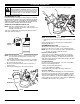
ASSEMBLY INSTRUCTIONS HANDLE ASSEMBLY 1. Remove the unit from the box. 2. Place the 2-holed end of the straight metal shaft over the shaft base on the unit and align the holes (Fig. 1). 3. Insert the two self-tapping screws (1/4” x 1-1/4”) into these holes (Fig. 1). 4. Using a 3/8” wrench, screw each self-tapping screw into the shaft until firm. DO NOT OVERTIGHTEN. 5.
OIL AND FUEL INFORMATION WARNING: OVERFILLING OIL CRANKCASE MAY CAUSE SERIOUS PERSONAL INJURY. Check and maintain the proper oil level in the crank case; it is important and cannot be overemphasized. Check the oil before each use and change it as needed. See Changing the Oil. 4. Pour the entire bottle of oil into the oil fill hole (Fig. 6). RECOMMENDED OIL TYPE Using the proper type and weight of oil in the crankcase is extremely important. Check the oil before each use and change the oil regularly.
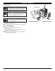
OIL AND FUEL INFORMATION FUELING THE UNIT WARNING: Add fuel in a clean, well ventilated outdoor area. Wipe up any spilled fuel immediately. Avoid creating a source of ignition for spilt fuel. Do not start the engine until fuel vapors dissipate. 1. d de lea Un Gas WARNING: Gasoline is extremely flammable. Ignited vapors may explode. Always stop the engine and allow it to cool before filling the fuel tank. Do not smoke while filling the tank. Keep sparks and open flames at a distance from the area.
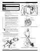
STARTING/STOPPING INSTRUCTIONS Choke Lever WARNING: Operate this unit only in a wellventilated outdoor area. Carbon monoxide exhaust fumes can be lethal in a confined area. Primer Bulb WARNING: Avoid accidental starting. Make sure you are in the starting position when pulling the starter rope (Fig. 11). To avoid serious injury, the operator and unit must be in a stable position while starting. STARTING INSTRUCTIONS 1. Check the oil level in the crankcase. Refer to Checking the Oil Level. 2. 3.
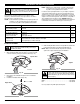
OPERATING INSTRUCTIONS HOLDING THE UNIT WARNING: Always wear eye, hearing, foot and body protection to reduce the risk of injury when operating this unit. Thumb Wheel Before operating the unit, stand in the operating position (Fig. 12). Check for the following: • The operator is wearing eye protection and proper clothing. • Both hands are holding the handle bar firmly. • The edger wheel adjusted for proper cut depth as shown in Figure 13 and edger positioned as shown in Figure 12.
MAINTENANCE AND REPAIR INSTRUCTIONS WARNING: To prevent serious injury, never perform maintenance or repairs with unit running. Always service and repair a cool unit. Disconnect the spark plug wire to ensure that the unit cannot start. MAINTENANCE SCHEDULE Perform these required maintenance procedures at the frequency stated in the table. These procedures should also be a part of any seasonal tune-up. NOTE: Some maintenance procedures may require special tools or skills.
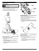
MAINTENANCE AND REPAIR INSTRUCTIONS CHECKING THE OIL LEVEL The importance of checking and maintaining the proper oil level in the crankcase cannot be overemphasized. Check oil before each use: 1. Stop the engine and allow oil to drain into the crankcase. 2. Place the unit on a level surface to get a proper oil level reading. 3. Keep dirt, grass clippings and other debris out of the engine. Clean the area around the oil fill plug before removing it. 4. Remove the oil fill plug. 5.
MAINTENANCE AND REPAIR INSTRUCTIONS Fig. 24 Fig. 25 NOTE: If the unit is operated without the air filter, you will VOID the warranty. 7. Reinstall the air filter cover. Position the tabs on the sides of the air filter cover onto the slots at the top of the back plate (Fig. 22). 8. Push the cover in until the tab on the air filter backplate snaps into place in the slot on the air filter cover (Fig. 22). CARBURETOR ADJUSTMENT The idle speed of the engine is adjustable.
MAINTENANCE AND REPAIR INSTRUCTIONS 7. Slide the feeler gauge between the rocker arm and the valve return spring. Measure the clearance between the valve stem and rocker arm (Fig. 29). Measure both the intake and exhaust valves. The recommended clearance for both intake and exhaust is .003 – .006 in. (.076 – 0.152 mm). Use a standard automotive .005 in. (0.127 mm) feeler gauge. The feeler gauge should slide between the rocker arm and valve stem with a slight amount of resistance, without binding.
TROUBLESHOOTING LE MOTEUR REFUSE DE DÉMARRER CAUSE Empty fuel tank ACTION Fill fuel tank with new fuel Primer bulb wasn't pressed enough Press primer bulb fully and slowly 10 times Old fuel Drain gas tank and add fresh fuel Fouled spark plug Replace or clean the spark plug Plugged spark arrestor Clean or replace spark arrestor LE MOTEUR REFUSE DE SE METTRE AU RALENTI CAUSE ACTION Air filter is plugged Replace or clean the air filter Old fuel Drain gas tank and add fresh fuel Improper carbure
SPECIFICATIONS ENGINE* Engine Type.................................................................................................................................................................. Air-Cooled, 4-Cycle Displacement .................................................................................................................................................................... 1.8 cu. in. (29 cc) Operating RPM ...................................................................................
MANUFACTURER’S LIMITED WARRANTY FOR: The limited warranty set forth below is given by Troy-Bilt LLC (“Troy-Bilt”) with respect with new merchandise purchased and used in the United States, its possessions and territories. Troy-Bilt warrants this product against defects in material and workmanship for a period of two (2) years commencing on the date of original purchase and will, at its option, repair or replace, free of charge, any part found to be defective in material or workmanship.
Manuel de L'utilisateur Coupe-bordures à 4 temps à essence TBE515 CONSERVEZ CES INSTRUCTIONS Obtenez la liste des concessionnaires agréés appelez le 1-800828-5500 aux États-Unis ou le 1-800-668-1238 au Canada. Pour de plus amples informations à propos de votre appareil, visitez www.troybilt.com. NE RETOURNEZ PAS L'APPAREIL AU DÉTAILLANT CHEZ QUI VOUS L'AVEZ ACHETÉ. TOUT SERVICE SOUS GARANTIE NÉCESSITE UNE PREUVE D'ACHAT.
CONSIGNES DE SÉCURITÉ • IMPORTANTES CONSIGNES DE SÉCURITÉ • LISEZ TOUTES LES INSTRUCTIONS AVANT L'UTILISATION • Prenez soin de bien lire et comprendre le manuel de l'appareil qui alimente cet accessoire. • Veuillez lire le manuel de l'utilisateur attentivement. Familiarisezvous avec les commandes et l'utilisation correcte de l’appareil. Sachez comment arrêter l’appareil et désactiver les commandes rapidement.
CONSIGNES DE SÉCURITÉ SYMBOLES DE SÉCURITÉ ET INTERNATIONAUX Ce manuel de l'utilisateur décrit les symboles et pictogrammes de sécurité et internationaux pouvant apparaître sur ce produit. Consultez le manuel de l'utilisateur pour les informations concernant la sécurité, le montage, le fonctionnement, l'entretien et les réparations. SYMBOLE SIGNIFICATION • SYMBOLE ALERTE DE SÉCURITÉ Indique un danger, un avertissement ou une mise en garde. Ce symbole peut être combiné à d'autres symboles ou pictogrammes.
FAMILIARISEZ-VOUS AVEC L’APPAREIL APPLICATIONS • La coupe le long des chemins, des sorties de garage, des zones rocailleuses, etc.
INSTRUCTIONS DE MONTAGE ASSEMBLAGE DU MANCHE 1. Sortir l’appareil du carton. 2. Placer l’extrémité à deux trous du manche droit en métal sur la base du manche sur l’appareil et aligner les trous (Fig. 1). 3. Insérer les deux vis autotaraudeuses (1/4” x 1-1/4”) dans ces trous (Fig. 1). 4. Utiliser une clef de 3/8” et bien serrer chaque vis autotaraudeuse dans le manche. NE PAS SERRER TROP FORT. 5.
INFORMATIONS SUR L’HUILE ET LE CARBURANT WARNING: LE REMPLISSAGE EXCESSIF DU CARTER-MOTEUR PEUT ANTRAÎNER DES BLESSURES GRAVES. Nous ne saurions trop insister sur l'importance de la vérification du niveau d'huile du carter-moteur et de son maintien. Vérifiez l'huile avant chaque utilisation et changezla au besoin tel qu'indiqué dans la section Changment d'Huile. TYPE D’HUILE RECOMMANDÉ Il est extrêmement important d'utiliser les bons type et indice d'huile dans le carter-moteur.
INFORMATIONS SUR L’HUILE ET LE CARBURANT AJOUR DE CARBURANT AVERTISSEMENT : Ajoutez d’essence dans un lieu propre et bien aéré en plein air. Essuyez immédiatement tout déversement d’essence. Évitez de mettre le feu au essence déversé. Ne démarrez pas le moteur avant dissipation des vapeurs d’essence. 1. d de lea Un Gas AVERTISSEMENT : L'essence est extrêmement inflammable et les vapeurs qui s'en dégagent peuvent exploser si on y met le feu.
INSTRUCTIONS DE DÉMARRAGE ET ARRÊT Levier d’étranglement AVERTISSEMENT : n’utiliser l’outil qu’à l’extérieur, dans un endroit bien aéré. Les émanations d’oxyde de carbone dans un endroit confiné peuvent être mortelles. Pompe d’amorce AVERTISSEMENT : éviter le démarrage accidentel. Se tenir en position de démarrage pour lancer le moteur (Fig. 12). Lors du démarrage, l’opérateur et l’outil doivent être en position d’équilibre afin d’éviter le risque de blessures graves. CONSIGNES POUR LE DEMARRAGE 1.
MODE D’EMPLOI COMMENT TENIR L’APPAREIL MISE EN GARDE : portez toujours des lunettes de sécurité, des bouchons antibruit, et des protections pour le corps et les pieds pour réduire les risques de blessures lors de l’utilisation de l’appareil. Roulette Levier d’ajustement de hauteur Avant de démarrer l’appareil, placez-vous en position de démarrage (Fig. 12). Vérifier que les consignes suivantes ont été respectées : • L’utilisateur porte des lunettes de sécurité et une tenue appropriée.
ENTRETIEN ET RÉPARATIONS AVERTISSEMENT : Afin d’éviter les blessures graves, n’effectuez jamais de réparation ou n’entretenez jamais l’appareil lorsqu’il est en fonctionnement. Les réparations et l’entretien doivent toujours être effectués lorsque l’appareil est froid. Déconnectez le fil de la bougie pour vous assurer que l’appareil ne se mette pas en marche. CALENDRIER D’ENTRETIEN Effectuez les étapes d’entretien obligatoires en suivant le tableau d’entretien.
ENTRETIEN ET RÉPARATIONS VÉRIFICATION DU NIVEAU D’HUILE Nous ne saurions trop insister sur l'importance de la vérification du niveau d'huile du carter moteur et de son maintien. Vérifiez l'huile avant chaque utilisation : 1. Arrêtez le moteur et laissez l’huile s’écouler dans le carter moteur. 2. Placez l'appareil sur une surface plane pour que le cultivateur soit en position horizontale afin de relever correctement le niveau d'huile. 3. Empêchez l'accumulation de saleté, de résidus de coupe, etc.
ENTRETIEN ET RÉPARATIONS Fig. 25 Fig. 24 gauche du filtre à air dans les fentes situées à gauche du boîtier du filtre à air (Fig. 22). 8. Pivotez le couvercle vers la droite jusqu’à ce que la languette du couvercle du filtre s’enfonce d’un déclic dans la fente sur le côté droite du boîtier du filtre (Fig. 22). RÉGLAGE DU CARBURATEUR La vitesse de ralenti du moteur est réglable à l’aide d’une vis de réglage accessible par un trou situé sur le dessus du couvercle du moteur (Fig. 26).
ENTRETIEN ET RÉPARATIONS soupape et le culbuteur (Fig. 26 & 27). Faites-le pour les soupapes d’admission et d'échappement. L'écart de jeu recommandé pour l'admission et l'échappement est de 0,076 – 0,152 mm (0,003 – 0,006 po). L'écart de jeu recommandé pour l'échappement est de 0,330 – 0,406 mm (0,013 – 0,016 po). Servez-vous d’une jauge d'épaisseur d’automobile standard de 0,127 et 0,381mm (0,005 et 0,015 po).
DÉPANNAGE LE MOTEUR REFUSE DE DÉMARRER CAUSE Réservoir de carburant vide SOLUTION Remplissez-le de carburant frais La poire d'amorçage n'a pas été pressée assez fort Pressez-la complètement et lentement de 10 fois Carburant vieux Drainez le réservoir/ajoutez du carburant frais Bougie encrassée Remplacez ou nettoyez-la Pare-étincelles colmaté Nettoyez ou remplacez le pare-étincelles LE MOTEUR REFUSE DE SE METTRE AU RALENTI CAUSE SOLUTION Filtre à air bouché Remplacez ou nettoyez-le Carburant vi
CARACTÉRISTIQUES MOTEUR* Type de moteur .................................................................................................................................................. Refroidi par air, 4-temps Cylindrée ............................................................................................................................................................................ 29 cc (1,8 po3) Régime de fonctionnement............................................................................
GARANTIE LIMITÉE DU FABRICANT POUR: La garantie limitée énoncée ci-après est accordée par Troy-Bilt LLC (« Troy-Bilt ») et concerne les marchandises neuves achetées et utilisées aux États-Unis, ainsi que dans leurs possessions et territoires.
Manual del Operador Recortador de bordes de césped a gasolina de 4 tiempos TBE515 CONSERVE ESTAS INSTRUCCIONES Llame 1-800-828-5500 en EE.UU. o al 1-800-668-1238 en Canada para obtener una lista de distribuidores de servicio localizados cerca de usted. Para obtener más detalles sobre su unidad, visite nuestro sitio en www.troybilt.com. NO REGRESE SU UNIDAD AL VENDEDOR. PARA SOLICITAR SERVICIO POR LA GARANTIA, DEBERA PRESENTAR PRUEBA DE SU COMPRA. ESTE PRODUCTO ESTA CUBIERTO POR UNA O MAS PATENTES DE EE.UU.
NORMAS PARA UNA OPERACIÓN SEGURA • IMPORTANTE INFORMACIÓN DE SEGURIDAD • LEA TODAS LAS INSTRUCCIONES ANTES DE LA OPERACIÓN • Lea cuidadosamente y entienda el manual del operador de la unidad que impulsa a este acople. • Lea este manual de instrucciones de funcionamiento detenidamente. Familiarícese completamente con los controles y el uso apropiado del equipo. Sepa cómo apagar la unidad y desactivar los controles con rapidez.
NORMAS PARA UNA OPERACIÓN SEGURA SIMBOLOS DE SEGURIDAD E INTERNACIONALES Este manual del operador describe los símbolos y figuras de seguridad e internacionales que pueden aparecer en este producto. Lea el manual del operador para obtener información completa acerca de la seguridad, ensamble, operación y mantenimiento y reparación. SIMBOLO SIGNIFICADO • SIMBOLO DE ALERTA DE SEGURIDAD Indica peligro, advertencia o precaución. Puede ser utilizado junto con otros símbolos o figuras.
CONOZCA SU UNIDAD APPLICACIONES • Para hacer recortes a lo largo de senderos, estacionamientos, jardincillos rocosos, etc.
INSTRUCCIONES DE MONTAJE CONJUNTO DEL MANGO 1. Saque la unidad de la caja. 2. Coloque el extremo de 2 orificios del eje metálico recto sobre la base del eje en la unidad y alinee los orificios (Fig. 1). 3. Inserte los dos tornillos autorroscantes (1/4” x 1-1/4”) en estos orificios (Fig. 2). 4. Utilizando una llave de 3/8”, atornille cada uno de los tornillos autorroscantes en el eje hasta que quede firme. NO APRIETE DEMASIADO. 5.
INFORMACION DEL ACEITE Y COMBUSTIBLE ADVERTENCIA: EL LLENAR DEMA- SIADO EL CÁRTER PUEDE CAUSAR LESIONES PERSONALES GRAVES No podemos exagerar la importancia del control y mantenimiento del nivel correcto de aceite en el cigüeñal. Verifique el aceite antes de cada uso y cámbielo cuando sea necesario según se indica en la sección de Cambio del aceite. TIPO DE ACEITE RECOMENDADO El uso de un aceite del tipo y peso correctos en el cigüeñal es extremadamente importante.
INFORMACION DEL ACEITE Y COMBUSTIBLE CARGA DE COMBUSTIBLE EN LA UNIDAD ADVERTENCIA: Cargue el combustible en un área exterior limpia y bien ventilada. Limpie de inmediato todo combustible que se haya derramado. Evite crear una fuente de encendido con el combustible derramado. No arranque el motor hasta que se hayan evaporado los gases del combustible. 1. d de lea Un Gas ADVERTENCIA: La gasolina es muy inflamable. Los gases pueden explotar si se encienden.
INSTRUCCIONES DE ARRANQUE Y APAGADO ADVERTENCIA: Use esta unidad sólo en un área Palanca del obturador Pera del cebador exterior bien ventilada. Los gases de escape de monóxido de carbono pueden ser letales en un área cerrada. ADVERTENCIA: Evite los arranques accidentales. Colóquese en posición de inicio cuando tire de la cuerda de arranque (Fig. 12). El operador y la unidad deben estar en una posición estable al arrancar la unidad para evitar graves lesiones personales. INSTRUCCIONES DE ARRANQUE 1.
INSTRUCCIONES DE OPERACIÓN COMO SOSTENER LA UNIDAD ADVERTENCIA: Use siempre protector para Mando rotatorio los ojos, oídos, los pies y el cuerpo a fin de reducir las posibilidades de lesiones al operar esta unidad. Antes de hacer funcionar la unidad, párese en la posición de funcionamiento (Fig. 12). Compruebe lo siguiente: • Que el operador use protector para los ojos y ropa adecuada. • Que ambas manos sujeten la barra de mango firmemente.
INSTRUCCIONES DE MANTENIMIENTO Y REPARACIÓN ADVERTENCIA: Para evitar lesiones graves, nunca realice trabajos de mantenimiento ni reparaciones con la unidad funcionando. Haga mantenimiento y repare a una unidad fría. Desconecte el cable de la bujía de encendido para asegurarse de que la unidad no pueda arrancar. PROGRAMA DE MANTENIMIENTO Lleve a cabo estos procedimientos de mantenimiento requeridos con la frecuencia indicada en la tabla.
INSTRUCCIONES DE MANTENIMIENTO Y REPARACIÓN INSPECCION DEL NIVEL DE ACEITE No podemos exagerar la importancia de verificar y mantener el nivel correcto de aceite en el cárter del cigüeñal. Inspeccione el nivel de aceite antes de cada uso: 1. Apague el motor y permita que el aceite drene dentro del cárter del cigüeñal. 2. Coloque la unidad sobre una superficie plana y nivelada para obtener una lectura correcta del nivel de aceite. 3. Mantenga la suciedad, recortes de césped, etc. fuera del motor.
INSTRUCCIONES DE MANTENIMIENTO Y REPARACIÓN Fig. 25 Fig. 24 Vuelva a instalar la cubierta del filtro de aire. Coloque los ganchos del lado derecha de la cubierta del filtro de aire en las ranuras del lado derecha de la placa posterior (Fig. 22). 8. Mueva la cubierta hacia la izquierdo derecha hasta que la orejeta del filtro de aire calce en su lugar en la ranura de la placa posterior (Fig. 22). AJUSTE DEL CARBURADOR La velocidad mínima del motor puede ser ajustada.
ENTRETIEN ET RÉPARATIONS 7. Deslice la galga entre el brazo oscilante y el resorte de retorno de la válvula. Mida el huelgo entre el vástago de la válvula y el brazo oscilante (Fig. 29). Realice esto en las válvulas de entrada y de escape. El huelgo recomendado para las válvulas de entrada y de escape es 0,076 – 0,152 mm (0,003 – 0,006 pulgadas). Use un calibrador regular de automóvil de 0,127 mm (0,005 pulgadas).
RESOLUCIÓN DE PROBLEMAS EL MOTOR NO ARRANCA CAUSA ACCIÓN El tanque de combustible está vacío Llene el tanque con combustible bien mezclado La bombilla de cebado no fue oprimida lo suficiente Oprima la bombilla de cebado total y lentamente de 10 veces El combustible es viejo Drene el tanque de gasolina / Agregue combustible nueva La bujía de encendido está arruinada Cambie o limpie la bujía de encendido Parachispas obstruido Limpie o cambie el parachispas EL MOTOR NO FUNCIONA EN MINIMA CAUSA ACC
ESPECIFICACIONES MOTOR* Tipo de motor . . . . . . . . . . . . . . . . . . . . . . . . . . . . . . . . . . . . . . . . . . . . . . . . . . . . . . . . . . . . . . . . . . . . . . . . . Enfriado por aire, 4 tiempos Desplazamiento . . . . . . . . . . . . . . . . . . . . . . . . . . . . . . . . . . . . . . . . . . . . . . . . . . . . . . . . . . . . . . . . . . . . . . 29 cc (1.8 pulgadas cúbicas) R.P.M. de operación . . . . . . . . . . . . . . . . . . . . . . . . . . . . . . . . . . . . . . . . . . . . . . . .
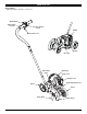
PARTS LIST REPLACEMENT PARTS - MODEL TBE515 4-CYCLE GAS EDGER 25 26 27 3 28 29 30 3 31 24 4 32 35 5 23 33 21 1 6 3 3 10 12 9 11 8 18 19 17 42 15 16 3 13 14 41 42 40 50 48 51 43 44 52 3 36 2 7 53 46 47 47 49 E16 39 34 22 20 37 38 3 45
PARTS LIST REPLACEMENT PARTS - MODEL TBE515 4-CYCLE GAS EDGER Item Part No.
PARTS LIST REPLACEMENT PARTS - MODEL TBE515 4-CYCLE GAS EDGER 1 5 4 7 3 2 6 1 8 13 9 10 11 16 17 15 12 20 21 22 16 18 19 47 29 46 30 26 25 15 17 16 27 14 34 41 40 43 44 45 E18 42 39 38 37 36 35 32 31 33 28 24 23
PARTS LIST REPLACEMENT PARTS - MODEL TBE515 4-CYCLE GAS EDGER Item Part No.
GARANTÍA LIMITADA DEL FABRICANTE PARA: La garantía limitada establecida a continuación es dada por TroyBilt LLC (“Troy-Bilt”) con respecto a mercancía nueva que sea comprada y usada en los Estados Unidos, sus posesiones y territorios.