Safe Operation Practices • Assembly & Set-Up • Controls & Operation • Service • Troubleshooting Operator’s Manual Safe Operation Practices......................................... 2 Assembly & Set-Up................................................... 4 Controls & Operation............................................... 6 Service....................................................................... 8 Troubleshooting....................................................... 9 Español.........................
1 Safe Operation Practices WARNING! This symbol points out important safety instructions which, if not followed, could endanger the personal safety and/or property of yourself and others. Read and follow all instructions in this manual before attempting to operate this machine. Failure to comply with these instructions may result in personal injury. When you see this symbol.
19. If situations occur which are not covered in this manual, use care and good judgment. Contact Customer Support for assistance or the name of your nearest service dealer. Children 2. 3. Tragic accidents can occur if the operator is not alert to the presence of children. Children are often attracted to power equipment such as lawn edgers. They do not understand the dangers. Never assume that children will remain where you last saw them. 1.
2 Assembly & Set-Up Thank You Thank you for purchasing this product. It was carefully engineered to provide excellent performance when properly operated and maintained. Please read this entire manual prior to operating the equipment. It instructs you how to safely and easily set up, operate and maintain your machine. Please be sure that you, and any other persons who will operate the machine, carefully follow the recommended safety practices at all times.
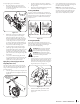
NOTE: The starter rope will not pull out of the engine unless the blade control (refer to Figure 2-5) is depressed against the upper handle. Securing Blade Depth Control Cable Unwrap the blade depth control cable from around the rear axle and route it up through the slot on the frame and up the right side of the handle. 1. Pull the depth control lever out of the first position of the depth control bracket. 2. Push lever all the way forward. 3. Release lever into last position of bracket. 4.
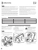
3 Controls & Operation Blade Control Blade Control Blade Depth Control Lever Blade Depth Control Lever Recoil Starter Recoil Starter Primer Bevel Adjustment Lever Curb Height Adjustment Lever 520 550 Figure 3-1 NOTE: This operator’s manual covers several models. Features may vary by model. Not all features in this manual are applicable to all models and the model depicted may differ from yours. Controls WARNING! Be familiar with all the controls and their proper operation.
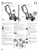
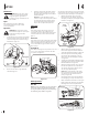
To begin edging, proceed as follows: 1. Move the edger to an area to be edged, making sure that the left rear wheel is on a hard surface and the blade is over the area to be cut. See Figure 3-3. 2. Pivot the right rear wheel into an applicable position in relation to the height of the curb to be edged along. 3. Release the curb height adjustment lever to lock the wheel in position. See Figure 3-4.
4 Service Maintenance 3. WARNING: Always stop engine, allow engine to cool, disconnect spark plug, and ground against engine before performing any type of maintenance on your machine. Engine Refer to the Engine Operator’s Manual for a detailed description of all engine-related service specifications. NOTE: Make certain that the drive belt is seated correctly on the blade spindle and that it is riding smoothly on the spindle sheaves and is not pinched between them.
NOTE: Make certain that the drive belt is seated correctly and that it is riding smoothly on the spindle sheaves and is not pinched between them. Repeat Steps 1-3 to adjust if the belt is pinched. WARNING! Never operate the edger without the spindle sheaves belt guard in place. Off-Season Storage Observe the following when preparing the edger for long-term storage: 1. Clean and lubricate the edger thoroughly as instructed on page 8 in the Maintenance section. 2.
Notes 10
Medidas de seguridad • Montaje y Configuración • Controles y Funcionamiento • Servicio • Solución de problemas Manual del operador Índice Medidas de seguridad............................................. 2 Montaje y Configuración......................................... 4 Controles y Funcionamiento................................... 6 Servicio...................................................................... 8 Solución de Problemas............................................ 9 Garantía...............
1 Medidas de seguridad ¡ADVERTENCIA! La presencia de este símbolo indica que se trata de instrucciones importantes de seguridad que se deben respetar para evitar poner en peligro su seguridad personal y/o material y la de otras personas. Lea y siga todas las instrucciones de este manual antes de poner en funcionamiento esta máquina. Si no respeta estas instrucciones puede provocar lesiones personales. Cuando vea este símbolo.
18. 19. Utilice solamente piezas y accesorios manufacturados para esta máquina por el fabricante. Si no lo hace, pueden producirse lesiones personales. Si se presentan situaciones que no están previstas en este manual, sea cuidadoso y use el sentido común. Póngase en contacto con Asistencia al Cliente para solicitar ayuda o el nombre del distribuidor de servicio más cercano a su domicilio. 2. 3. Niños Pueden ocurrir accidentes trágicos si el operador no está atento a la presencia de niños.
2 Montaje y Configuración Gracias Gracias por comprar este producto. La misma ha sido diseñada cuidadosamente para brindar excelente rendimiento si se la opera y mantiene correctamente. Por favor lea todo este manual antes de operar el equipo. Le indica cómo configurar, operar y mantener la máquina con seguridad y fácilmente. Por favor asegúrese de seguir cuidadosamente y en todo momento las prácticas de seguridad recomendadas, y hacérselas seguir a cualquier otra persona que opere la máquina.
2. Colocación del cable de Control de Profundidad Cuchilla Desenvolver el cable de control de profundidad cuchilla de todo el eje trasero y ruta hacia arriba a través de la ranura en el bastidor y la ruta hacia arriba el lado derecho del mango. 1. Tirar de la palanca de control de profundidad de la primera posición del soporte de control de profundidad. 2. Empuje la palanca completamente hacia adelante. 3. Soltar la palanca en la última posición del soporte. 4.
3 Controles y Funcionamiento Control de cuchilla Control de cuchilla Palanca de control de cuchilla Palanca de control de cuchilla Arrancador de retroceso Arrancador de retroceso Cebador Palanca de ajuste del biselado Palanca de ajuste de altura del bordillo 520 550 Figura 3-1 Controles Palanca de control de profundidad de la cuchilla NOTA: Este manual del operador cubre varios modelos. Las características técnicas pueden variar de acuerda al modelo.
Para comenzar a bordear, proceda de la siguiente forma: Para ajustar la altura de la rueda del bordillo, haga lo siguiente: 1. 1. Mueva la unidad al área que va a recortar, asegurándose de que la rueda posterior izquierda esté sobre una superficie dura y que la cuchilla está sobre el área a cortar. Vea la Figura 3-3. Baje la rueda posterior derecha moviendo la palanca de ajuste de la altura del bordillo ligeramente a la izquierda. Vea la Figura 3-4.
4 Servicio Mantenimiento Lubricación ¡ADVERTENCIA! Desconecte el cable de la bujía de encendido y haga masa contra el motor antes de realizar cualquier ajuste, reparación o mantenimiento. Motor Consulte el manual del motor entregado con su bordeadora para obtener una descripción detallada de todas las especificaciones de servicio relacionadas con el motor. El borde de la bordeadora ¡ADVERTENCIA! El borde de la bordeadora es filoso.
7. Asegúrese de que la correa de transmisión está sobre la polea volante del motor y las poleas locas, y vuelva a ajustar la tuerca de seguridad con brida que se encuentra en la parte superior del bastidor. NOTA: Asegúrese de que la correa de transmisión está correctamente asentada y que se encuentra cómodamente ubicada sobre los bordes del husillo y no pellizcada entre ellos. Repita los tres primeros pasos si la correa está pellizcada.
Notas 10