
Full Product Manual

12 Section 2 — ASSembly & Set-Up
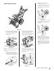
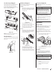
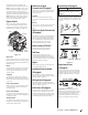
7. Push chute control rod toward control
panel until hole in rod lines up with hole
in chute control input closest to chute
control head and insert hairpin clip (a)
removed in Step 1. See Figure 2-33.
(a)
Figure 2-33
NOTE: Second hole is used to achieve
further engagement of chute control
rod into pinion gear if required. Refer to
Service section for Chute Control Rod
adjustments.
8. Finish securing chute control head to
chute support bracket with wing nut (b),
clevis pin (d), and bow-tie cotter pin (e)
removed in Step 1.
STOP
Continue to Set-Up (page 14)
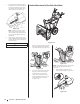
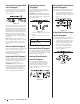
Overhead Chute Control (w/ Flex Shaft & Steel Chute)
Figure 2-34
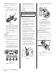
1. Remove lock nuts (a) and hex screws (b)
from chute support bracket (this will
require two wrenches). See Figure 2-35.
Chute
Assembly
Chute Base
Chute Support
Bracket
Chute Control Head
(a)
(a)
(b)
(b)
Figure 2-35
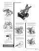
2. Place chute assembly onto chute base
and chute control head onto chute
support bracket. See Figure 2-36.
3. Secure chute control head to chute
support bracket with lock nuts (a) and
hex screws (b) removed in Step 1.
See Figure 2-36.
(a)
(a)
(b)
(b)
Figure 2-36
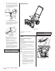
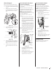
NOTE: For smoothest operation, cables should
all be to the left of the chute directional
control rod.
4. Remove hairpin clip (a) from rear of
chute control assembly. See Figure 2-37.
(a)
(b)
Figure 2-37