
Use and Care Manual
29
SERVICE AND MAINTENANCE
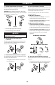
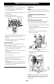
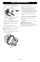
6. Carefully position hex shaft downward and to left before
carefully sliding friction wheel assembly off shaft (Figure 88).
Figure 88
NOTE: If you’re replacing friction wheel assembly as a whole,
discard the worn part and slide new part onto hex shaft.
7. Follow previous steps in reverse order to reassemble
components.
8. Perform Drive Control test shown on page 18.
If you’re disassembling friction wheel and replacing only rubber
ring, proceed as follows:
NOTE: Not all friction wheels are serviceable. If this is the case,
simply replace friction wheel assembly.
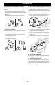
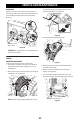
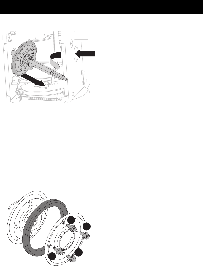
9. Remove four screws (b) which secure friction wheel’s side
plates together (Figure 89).
b
b
b
b
Figure 89
10. Remove rubber ring from between the plates.
11. Reassemble side plates with a new rubber ring.
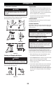
NOTE: When reassembling friction wheel assembly, make
sure that rubber ring is centered and seated properly
between the side plates. Tighten each screw only one
rotation before turning wheel clockwise and proceeding with
next screw. Repeat this process several times to ensure plates
are secured with equal force (between 115-145 in-lbs).
12. Apply a light coating of Bostik Regular Grade Never-Seez® to
hex shaft.
13. Slide friction wheel assembly back onto hex shaft and follow
the steps above in reverse order to reassemble components.
14. After replacing friction wheel, perform Drive Control test
shown on page 18.
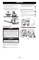
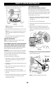
NOTE: Make sure shift lever pin is in place in bearing housing
(Figure 87 inset).
HYDRO TRANSMISSION IF EQUIPPED
NOTE: See your authorized service dealer to have the Hydro
Transmission serviced or contact Customer Support for assistance
and the name of your nearest servicing dealer.