Safe Operation Practices • Set-Up • Operation • Maintenance • Service • Troubleshooting • Warranty Operator’s Manual RZT Series Tractor — Colt ZT42 WARNING READ AND FOLLOW ALL SAFETY RULES AND INSTRUCTIONS IN THIS MANUAL BEFORE ATTEMPTING TO OPERATE THIS MACHINE. FAILURE TO COMPLY WITH THESE INSTRUCTIONS MAY RESULT IN PERSONAL INJURY. TROY-BILT LLC, P.O. BOX 361131 CLEVELAND, OHIO 44136-0019 Printed In USA Form No.
1 To The Owner Thank You Thank you for purchasing a RZT series tractor manufactured by Troy-Bilt LLC. It was carefully engineered to provide excellent performance when properly operated and maintained. Troy-Bilt LLC reserves the right to change product specifications, designs and equipment without notice and without incurring obligation. Please read this entire manual prior to operating the equipment. It instructs you how to safely and easily set up, operate and maintain your machine.
Important Safe Operation Practices 2 WARNING! This symbol points out important safety instructions which, if not followed, could endanger the personal safety and/or property of yourself and others. Read and follow all instructions in this manual before attempting to operate this machine. Failure to comply with these instructions may result in personal injury. When you see this symbol.
12. A missing or damaged discharge cover can cause blade contact or thrown object injuries. 13. Stop the blade(s) when crossing gravel drives, walks, or roads and while not cutting grass. 14. Watch for traffic when operating near or crossing roadways. This machine is not intended for use on any public roadway. 15. Do not operate the machine while under the influence of alcohol or drugs. 16. Mow only in daylight or good artificial light. 17. Never carry passengers. 18. Back up slowly.
Children a. Use only an approved gasoline container. 1. b. Never fill containers inside a vehicle or on a truck or trailer bed with a plastic liner. Always place containers on the ground away from your vehicle before filling. c. When practical, remove gas-powered equipment from the truck or trailer and refuel it on the ground. If this is not possible, then refuel such equipment on a trailer with a portable container, rather than from a gasoline dispenser nozzle. d.
Check the blade(s) and engine mounting bolts at frequent intervals for proper tightness. Also, visually inspect blade(s) for damage (e.g., excessive wear, bent, cracked). Replace the blade(s) with the original equipment manufacturer’s (O.E.M.) blade(s) only, listed in this manual. “Use of parts which do not meet the original equipment specifications may lead to improper performance and compromise safety!” Do not modify engine 6. Mower blades are sharp.
Safety Symbols This page depicts and describes safety symbols that may appear on this product. Read, understand, and follow all instructions on the machine before attempting to assemble and operate. Symbol Description READ THE OPERATOR’S MANUAL(S) Read, understand, and follow all instructions in the manual(s) before attempting to assemble and operate WARNING— ROTATING BLADES Do not put hands or feet near rotating parts or under the cutting deck. Contact with the blade(s) can amputate hands and feet.
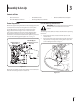
Section 2 — Safe Operation Practices Operate zero turn tractors across the face of slopes rather than up and down. Begin with the first pass across the bottom of the slope and turn uphill at the end of each pass whenever possible. WARNING! Do not operate your lawn mower on such slopes. Do not mow on inclines with a slope in excess of 15 degrees (a rise of approximately 2-1/2 feet every 10 feet). Use this page as a guide to determine slopes where you may not operate safely.
3 Assembly & Set-Up Contents of Crate • • One Lawn Tractor • One Oil Drain Tube • One RZT Operator’s Manual • One Engine Operator’s Manual Tractor Preparation One Deck Wash Hose Coupler Lower Deck Discharge Chute Deflector WARNING! Never operate the mower deck without the chute deflector installed and in the down position. Remove the upper crating material from the shipping pallet, and cut any bands or tie straps securing the tractor to the pallet.
3. Install the discharge chute deflector using the carriage bolts, push nuts and flange lock nuts as shown in Fig. 3-3 and securely tighten the hardware. 3. Rotate the seat into position and secure the seat into place with the previously removed shoulder bolts and lock nuts. Be careful not to crimp or damage the wire harness while installing the seat. See Fig. 3-5.
3. Slide the flat washer onto the hex screw. From the outside, insert the hex screw with washer through the control lever slot and the hole of the pivot bracket. Secure with the flange lock nut. See Fig. 3-6. 4. Note the relative position of the control lever to the pivot bracket, then repeat the previous steps to reposition the other control lever in approximately the same position. 5.
4 Controls & Features Deck Height Index Deck Lift Handle Parking Brake Throttle/Choke Control or Throttle Control Choke Control Hour Meter/ Indicator Panel Seat Adjustment Lever PTO Switch LH Drive RH Drive Control Lever Control Lever Ignition Switch Cup Holder Fuel Tank Cap Storage Tray Figure 4-1 NOTE: References to LEFT, RIGHT, FRONT, and REAR indicate that RH and LH Drive Control Levers position on the tractor when facing forward while seated in the The RH and LH control levers are located on
Ignition Switch Fuel Tank Cap The ignition switch is located on the RH console to the right of the operator’s seat. The ignition switch has three positions. The fuel tank cap is located near the middle of the LH console. Turn the fill cap approximately 1⁄4 turn and pull upward to remove. The fuel cap is tethered to the tractor to prevent its loss. Do not attempt to remove the cap from the tractor. STOP — The engine and electrical system is turned off. RUN — The tractor electrical system is energized.
Indicator Panel Features Parking Brake Engagement Lever Battery Indicator The parking brake engagement lever is located on the front/left of the seat box frame, and is used to engage the parking brake. Illuminates and the battery voltage is displayed briefly when the ignition switch it turned to the “ON” position. Illuminates to indicate the battery voltage has dropped below 11.5 (+0.5/-1.0) volts, and the voltage is displayed on the hour meter.
5 Operation General Safety Before Operating Your Tractor • RECEIVE INSTRUCTION — Entirely read this operator’s manual. Learn to operate this machine SAFELY. Do not risk INJURY or DEATH. Allow only those who have become competent in its usage to operate this tractor. • Before you operate the tractor, study this manual carefully to familiarize yourself with the operation of all the instruments and controls. It has been prepared to help you operate and maintain your tractor efficiently.
• The safety interlock system will shut off the engine if the operator leaves the seat with the PTO engaged, regardless of whether the parking brake is engaged. 5. Turn the ignition key clockwise to the “START” position and release it as soon as the engine starts; however, do not crank the engine continuously for more than 5 seconds at a time. If the engine does not start within this time, turn the key to “OFF” and wait at least 15 seconds to allow the engine’s starter motor to cool.
Stopping the Engine 1. Place the PTO switch in the “OFF” position. 2. Move the RH and LH drive control levers fully outward in the neutral position. 3. Engage the parking brake. 4. Move the throttle/choke control to midway between the SLOW and FAST positions. 5. Turn the ignition key to the “OFF” position and remove the key from the ignition switch. 3. Move the RH and LH drive control levers inward in the neutral position. Refer to Figure 5-2.
1. Driving the Tractor Forward Warning! Keep all movement of the drive control levers slow and smooth. Abrupt movement of the control levers can affect the stability of the tractor and could cause the tractor to flip over, which may result in serious injury or death to the operator. 1. To turn to the left, move the left drive control lever rearward of the right lever. See Fig. 5-4. Forward Left Turn Slowly and evenly move both drive control levers forward. The tractor will start to move forward.
Driving the Tractor In Reverse Turning While Driving Rearward WARNING! Always look behind and down on both sides of the tractor before backing up. Always look behind while traveling in the reverse direction. To turn the tractor while driving rearward, move the control levers as necessary so that one lever is forward of the other. The tractor will turn in the direction of the forward control lever. 1. 1. Slowly and evenly move both drive control levers rearward.
Executing a Zero Turn Stopping the Tractor Warning! When executing a zero turn, the tractor MUST BE STOPPED. Executing a zero turn while the tractor is moving can significantly reduce your control of the tractor and will cause severe turf defacement to occur. 1. Stop the forward or reverse motion of the tractor by moving the two drive control levers to neutral. 2. To turn clockwise, move the left control lever forward while simultaneously moving the right control lever rearward. See Fig. 5-9. 1.
Using the Mower Deck Warning! Make certain the area to be mowed is free of debris, sticks, stones, wire or other objects that can be thrown by the rotating blades. NOTE: Do not engage the mower deck when lowered in grass. Premature wear and possible failure of the ‘V” belt and PTO clutch will result. Fully raise the deck or move to a non grassy area before engaging the mower deck. Checking the Safety Interlock Circuits Periodically check the safety interlock circuits to ensure they are working properly.
6 Maintenance & Adjustments Maintenance Schedule Before Each use Check Engine Intake Screen/Cover Every 10 Hours Every 50 Hours P P Lube Front Pivot Axle and Caster Axles P Clean Engine Cooling Fins P Lube Deck Wheels Maintenance Warning! Before performing any maintenance or repairs, disengage the PTO, move the drive control levers fully outward in the neutral position, engage the parking brake, stop the engine and remove the key to prevent unintended starting.
General Battery Information Using the Deck Wash System Warning! • Should battery acid accidentally splatter into the eyes or onto the skin, rinse the affected area immediately with clean cold water. If there is any further discomfort, seek prompt medical attention. • If acid spills on clothing, first dilute it with clean water, then neutralize with a solution of ammonia/ water or baking soda/water.
Using the Transmission Bypass Rods Battery Storage If for any reason the tractor will not drive or you wish to move the tractor, the two hydrostatic transmissions are equipped with a bypass rod that will allow you to manually move the tractor short distances. • When storing the tractor for extended periods, disconnect the negative battery cable. It is not necessary to remove the battery. • All batteries discharge during storage. Keep the exterior of the battery clean, especially the top.
c. Empty the fuel system: • Prior to putting the tractor in storage, monitor fuel consumption with the goal of running the fuel tank empty. • Run the engine until it begins to stall. Use the choke to keep the engine running until all fuel in the carburetor has been exhausted. • Clean the engine and the entire tractor thoroughly. 4. Fully charge the battery, then disconnect the negative cable at the battery to prevent possible discharge. Recharge the battery periodically when in storage.
Leveling the Mower Deck Front to Back Leveling When correctly adjusted the mower deck should be level side to side, and the front of the deck should be approximately 1⁄4 inch lower than the rear of deck. The front of the deck should be approximately 1⁄4” lower than the rear of the deck. Adjust if necessary as follows: NOTE: Check the tractor’s tire pressure before performing any deck leveling adjustments. See the tire side wall for proper inflation pressures. 1.
Adjusting the Gauge Wheels Warning! Keep hands and feet away from the discharge opening of the cutting deck. NOTE: The deck gauge wheels are an anti-scalp feature of the deck and are not designed to support the weight of the cutting deck. The mower deck cutting height can be set in any of six height settings using the tractor’s deck lift handle. The deck heights range from 1-1⁄2” to 4”.
7 Service Battery Removal Charging the Battery Warning! Battery posts, terminals and related accessories contain lead and lead compounds. Wash hands after handling. Test and, if necessary, recharge the battery after the tractor has been stored for a period of time. • The battery is located on the right/rear of the tractor beneath the seat box frame. To remove the battery: 1. Remove the two hex tapping screws from the battery hold-down bracket and remove the bracket.
2. Working from the middle of the tractor, pivot the idler bracket and movable idler pulley rearward away from the backside of the ‘V” belt just far enough to lift the belt up and over the idler pulley. See Fig. 7-3. 4. While still holding the belt downward, continue turning the PTO pulley until the belt is rolled off the pulley. Refer to Fig. 7-4. V-Belt PTO Pulley PTO Belt Movable Idler Pulley Fixed Idler Pulley Pull Idler Pulley Rearward Transmission Tube Idler Bracket Figure 7-4 Figure 7-3 3.
Deck Installation To install the mower deck, proceed as follows: 1. While holding the deck front hanger rod upward, carefully slide the deck underneath the right side of the tractor. 2. While still holding the front hanger rod, slide the deck forward until the front hanger rod can be lowered into the slots of the front deck bracket. 3. Lower the front hanger rod into the slots of the front deck bracket, then slide the deck rearward. 4.
2. Use a 15⁄16” wrench to hold the hex nut on top of the spindle assembly when loosening the hex nut securing the blade. A block of wood may be placed between the deck housing and the cutting edge of the blade to help in breaking loose the hex nut securing the blade. See Fig. 7-7. Wood Block Hex Flange Nut 3. Using the ratchet for leverage, pivot the idler bracket and idler pulley away from the backside of the ‘V” belt; then lift the belt off and above the engine pulley and off the idler pulley. 4.
5. Remove the flange lock nut and hex screw securing the transmission control rod to the transmission control arm. Wheel rotation should stop. If it does not, contact your Troy-Bilt Service Dealer. 6. If the rotation stops, adjust the control rod up or down as necessary to align with the hole in the transmission control arm. Re-insert the hex nut into the hole in the control arm and secure with the hex lock nut. 7.
8 Troubleshooting Problem Excessive vibration Uneven cut Mower will not mulch grass (If Equipped w/Mulching Kit) Cause Remedy 1. Cutting blade loose or unbalanced. 1. Tighten blade and spindle. 2. Damaged or bent cutting blade. 2. Replace blade. 1. Deck not leveled properly. 1. Perform side-to-side deck adjustment. 2. Dull blade. 2. Sharpen or replace blade. 3. Uneven tire pressure. 3. Check tire pressure in all four tires. 1. Engine speed too low. 1.
9 Replacement Parts Component Part Number and Description KH-32-883-03-S1 Air Filter w/ Pre-Cleaner KH-12-050-01-S Oil Filter KH-25-050-22-S1 Fuel Filter 759-3336 Spark Plug (RC12YC) 954-04137A Drive Belt (Mowing Deck) 954-04043A Drive Belt (Transmission) 734-04155 Deck Wheel 751-10703A 751-10447A Fuel Tank Cap (Non-Calfornia Models) Fuel Tank Cap (California Models) Phone (800) 828-5500 to order replacement parts or a complete Parts Manual (have your full model number and serial number read
Component Part Number and Description 925-1707D Battery 746-04539 Throttle/Choke Control Cable 925-1745A Ignition Key 942-04308 Blade 918-04822A Deck Spindle 631-04344 Discharge Chute Assembly 634-04293 Wheel Assembly 634-04237B Caster Wheel Assembly Phone (800) 828-5500 to order replacement parts or a complete Parts Manual (have your full model number and serial number ready). Parts Manual downloads are also available free of charge at www.troybilt.com.
10 Attachments & Accessories The following attachments and accessories are compatible with your Troy-Bilt RZT tractor. See your Troy-Bilt dealer or the retailer from which you purchased your tractor for information regarding price and availability.
Notes 11 37
FEDERAL and/or CALIFORNIA EMISSION CONTROL WARRANTY STATEMENT YOUR WARRANTY RIGHTS AND OBLIGATIONS MTD Consumer Group Inc, the United States Environmental Protection Agency (EPA), and, for those products certified for sale in the state of California, the California Air Resources Board (CARB) are pleased to explain the emission (evaporative and/or exhaust) control system (ECS) warranty on your outdoor 2006 and later small off-road spark-ignited engine and equipment (outdoor equipment engine) In California, n
WARRANTED PARTS: The repair or replacement of any warranted part otherwise eligible for warranty coverage may be excluded from such warranty coverage if MTD Consumer Group Inc demonstrates that the outdoor equipment engine has been abused, neglected, or improperly maintained, and that such abuse, neglect, or improper maintenance was the direct cause of the need for repair or replacement of the part.
MANUFACTURER’S LIMITED WARRANTY FOR The limited warranty set forth below is given by Troy-Bilt LLC with respect to new merchandise purchased and used in the United States and/or its territories and possessions, and by MTD Products Limited with respect to new merchandise purchased and used in Canada and/ or its territories and possessions (either entity respectively, “TroyBilt”). c.
Medidas importantes de seguridad • Configuración • Funcionamiento • Mantenimiento • Servicio • Solución de problemas • Garantía Manual del Operador Tractor Serie RZT — Colt ZT42 ADVERTENCIA LEA Y RESPETE TODAS LAS NORMAS DE SEGURIDAD E INSTRUCCIONES INCLUIDAS EN ESTE MANUAL ANTES DE PONER EN FUNCIONAMIENTO ESTA MÁQUINA. SI NO RESPETA ESTAS INSTRUCCIONES PUEDE PROVOCAR LESIONES PERSONALES. TROY-BILT LLC, P.O. BOX 361131 CLEVELAND, OHIO 44136-0019 Impreso en Estados Unidos de América Formulario No.
1 Al propietario Gracias Gracias por comprar un tractor serie RZT fabricado por Troy-Bilt LLC. El mismo ha sido diseñado cuidadosamente para brindar excelente rendimiento si se lo opera y mantiene correctamente. Por favor lea todo este manual antes de operar el equipo. Le indica cómo configurar, operar y mantener la máquina con seguridad y fácilmente.
2 Medidas importantes de seguridad ADVERTENCIA: La presencia de este símbolo indica que se trata de instrucciones importantes de seguridad que se deben respetar para evitar poner en peligro su seguridad personal y/o material y la de otras personas. Lea y siga todas las instrucciones de este manual antes de poner en funcionamiento esta máquina. Si no respeta estas instrucciones puede provocar lesiones personales. Cuando vea este símbolo.
4 10. Esté atento a la cortadora y a la dirección de la descarga de los aditamentos y no apunte a nadie. Nunca haga funcionar la cortadora de césped sin que estén colocados la cubierta de descarga o todo el colector de recortes de césped. 25. Desenganche todos los embragues de los accesorios, coloque el freno de mano en posición ‘on’ y mueva las palancas de control de transmisión totalmente hacia afuera a la posición neutral antes de intentar arrancar la máquina. 11.
6. Haga que todos los movimientos en las pendientes sean lentos y graduales. No cambie repentinamente la velocidad ni la dirección. La aceleración o la reducción repentina de velocidad puede hacer que el frente de la máquina se levante y dé una voltereta hacia atrás, lo que podría producir lesiones graves. 2. No permita nunca que los niños menores de 14 años utilicen esta máquina.
Llene el tanque no más de ½ pulgada por debajo de la base del cuello del tapón de carga, para dejar espacio para la expansión del combustible. 8. Nunca modifique el sistema de bloqueo de seguridad ni otros mecanismos de seguridad. Controle periódicamente que funcionen correctamente. i. Vuelva a colocar la tapa de la gasolina y ajústela bien. 9. j. Limpie el combustible que se haya derramado sobre el motor y el equipo. Traslade la máquina a otra zona. Espere 5 minutos antes de encender el motor.
Amortiguador de chispas Advertencia: Esta máquina está equipada con un motor de combustión interno y no debe ser utilizada en o cerca de un terreno agreste cubierto por bosque, malezas o hierba excepto que el sistema de escape del motor esté equipado con un amortiguador de chispas que cumpla con las leyes locales o estatales correspondientes (en caso de existir). Si se utiliza un amortiguador de chispas el operador lo debe mantener en condiciones de uso adecuadas.
8 Sección 2 — Medidas de seguridad ínea de por la l puntos (repres enta Funcione los tractores de la vuelta de RZT cero a través de la cara de cuestas algo que hacia arriba y hacia abajo. Comience con el primer paso a través de la parte inferior de la cuesta y dé vuelta cuesta arriba en el extremo de cada paso siempre que sea posible. ADVERTENCIA: No opere la cortadora de césped en dichas pendientes. No corte en inclinaciones mayores de 15 grados (elevación aproximada de 2 1/2 pies por cada 10 pies).
3 Montaje y Configuración Contenido del cajón • Un tractor corta césped • Un tubo de drenaje de aceite • Un Manual del operador del RZT Manual • Un Manual del operador del motor Preparación del tractor • Un acoplador de manguera para lavado de plataforma Bajo la cubierta del canal de descarga del deflector ¡ADVERTENCIA! No utilice nunca la cubierta de la Retire el material de embalaje superior del pálet de embarque, y corte cualquier banda o tira que fije el tractor al pálet.
3. Instale el deflector del canal de descarga con los pernos del carro, empuje las tuercas y la brida de tuercas como se muestra en la figura. 3-3 y apriete bien el hardware. 6. Gire el asiento en su posición y asegure el asiento en su lugar con los pernos de reborde y tuercas de fijación que extrajo antes. Tenga cuidado de no doblar o dañar el cableado mientras instala el asiento. Vea la Fig. 3-5..
3. Deslice la arandela plana hacia el tornillo hexagonal. Desde afuera, inserte el tornillo hexagonal con arandela a través de la ranura de la palanca de control y el orificio del soporte de pivote. Fije con la tuerca de seguridad con brida. Vea la Fig. 3-6. 4. Observe la posición relativa de la palanca de control respecto del soporte de pivote, luego repita los pasos previos para volver a colocar en posición la otra palanca de control en aproximadamente la misma posición. 5.
4 Controles y Características Manija de Posicionamiento elevación de de la altura de la la plataforma plataforma Freno de mano Control del regulador o Del acelerador y del estrangulador Estrangulador Medidor horario/ Panel indicador Palanca de control de transmisión izquierda Palanca de control de transmisión derecha Palanca de ajuste del asiento Interruptor de potencia de arranque Interruptor de encendido Portacubeta Tapón del tanque de combustible Indicador de nivel de combustible Bandeja de alma
Interruptor de encendido Tapón del tanque de combustible El interruptor de encendido está ubicado en la consola del lado derecho, a la derecha del asiento del operador. El interruptor de encendido tiene tres posiciones. El tapón del depósito de combustible está ubicado cerca de la parte media de la consola del lado izquierdo. Gire el tapón aproximadamente 1⁄4 de vuelta y tire hacia arriba para extraerlo. El tapón del combustible está amarrado al tractor para impedir que se pierda.
Características del panel indicador Indicador de batería Se ilumina y muestra brevemente el voltaje de la batería cuando el interruptor de encendido se coloca en posición "ON" (encendido). Se ilumina para indicar que el voltaje de la batería ha bajado por debajo de 11,5 (+0,5/-1,0) voltios de CC (el voltaje de la batería también se muestra en el medidor horario).
5 Funcionamiento Seguridad general Antes de hacer funcionar el tractor • RECIBA LAS INSTRUCCIONES - Lea este manual del operador en su totalidad. Aprenda a operar esta máquina CON SEGURIDAD. No se arriesgue a quedar expuesto a LESIONES o a la MUERTE. Solamente se debe permitir operar este tractor a quienes se hayan familiarizado a fondo con el uso del mismo.
• Si el operador abandona su asiento con la potencia de arranque (PTO) enganchada, se encuentre o no colocado el freno de mano, el sistema de bloqueo de seguridad apaga el motor. 5. NOTA: El interruptor de la potencia de arranque (PTO) se debe mover a la posición "OFF" (apagado) para volver a arrancar el motor.
Detención del motor 1. Coloque el interruptor de la potencia de arranque (PTO) en posición "OFF" (apagado). 2. Coloque las palancas de control de transmisión del lado derecho y del lado izquierdo totalmente hacia afuera, en posición neutral. 3. Coloque el freno de mano. 4. Mueva el control del regulador/cebador a distancia media entre las posiciones VELOCIDAD LENTA y VELOCIDAD RÁPIDA. 5. Gire la llave de encendido a la posición "OFF" (apagado) y quite la llave del interruptor de encendido. 3.
1. Conducción del tractor hacia adelante ¡Advertencia! Todos los movimientos de las palancas de control deben ser lentos y suaves. El movimiento abrupto de las palancas de control puede afectar la estabilidad del tractor y podría hacer que el tractor se voltee, con el resultado de lesiones graves o incluso la muerte del operador. 1. GIRO HACIA LA IZQUIERDA DESPLAZÁNDOSE HACIA ADELANTE Mueva las palancas de control lenta y suavemente hacia adelante. El tractor comenzará a desplazarse hacia adelante.
Conducción del tractor en marcha atrás Realizar un giro mientras se conduce marcha atrás ¡ADVERTENCIA! Siempre mire hacia atrás y hacia abajo a ambos lados del tractor antes de desplazarse marcha atrás. Siempre mire hacia atrás cuando se desplaza en marcha atrás. 1. Mueva las dos palancas de control lenta y suavemente hacia atrás. El tractor comenzará a moverse hacia atrás. Vea la Fig. 5-6.
Giro de radio cero Detención del tractor ¡Advertencia! Para realizar un giro de radio 1. 2. cero, el tractor SE DEBE DETENER. La realización de un giro de radio cero con el tractor en movimiento puede reducir significativamente el grado de control que se tenga sobre el mismo, y dará lugar a un grave deterioro del césped. Detenga el movimiento del tractor hacia adelante o hacia atrás colocando las dos palancas de control en neutral.
Uso de la plataforma de la cortadora ¡Advertencia! Asegúrese que el área donde se va a cortar esté libre de desechos, ramitas, piedras, cables u otros objetos que puedan ser arrojados por las cuchillas rotativas. NOTA: No enganche la plataforma de la cortadora cuando esté baja sobre el pasto. Se produce el desgaste prematuro y la posible falla de la correa en "V" y del embrague de la potencia de arranque (PTO).
6 Mantenimiento y Ajustes Calendario de mantenimiento Antes de Cada uso Inspeccione la pantalla/cubierta de entrada del motor Cada 10 horas Cada 25 horas P P Lubrique el eje de pivote delantero y los ejes de las rueditas P Limpie las aletas de refrigeración del motor P Lubrique las ruedas de la plataforma Mantenimiento Vaciado del aceite del motor 1. Localice el puerto de drenaje de aceite en el lado izquierdo del motor. 2.
Información general sobre la batería Uso del sistema de lavado de la plataforma ¡Advertencia! Cuando use el sistema de lavado ¡Advertencia! • • • • • • • En caso de que se produzca una salpicadura accidental de ácido en los ojos o la piel, enjuague el área afectada inmediatamente con agua limpia fría. Si tiene algún malestar adicional, consulte un médico inmediatamente.
Uso de las varillas de derivación de la transmisión Almacenamiento de la batería Si por alguna razón el tractor no funciona o usted desea moverlo, las dos transmisiones hidrostáticas están equipadas con una varilla de derivación que permite mover manualmente el tractor a lo largo de distancias cortas. • Cuando el tractor se guarda durante períodos prolongados, desconecte el cable negativo de la batería. No es necesario retirar la batería. • Todas las baterías se descargan durante el almacenamiento.
c. Vaciado del sistema de combustible: • Antes de guardar el tractor, observe el consumo de combustible a los efectos de hacer funcionar el tractor hasta que el depósito esté vacío. • Haga funcionar el motor hasta que comience a detenerse. Use el cebador para mantener el motor en funcionamiento hasta que se haya agotado todo el combustible del carburador. • 2. Palanca de control Drene el combustible del recipiente del carburador, consultando el manual del motor. 3.
Nivelación de la plataforma de la cortadora de césped Nivelación de adelante hacia atrás Cuando se encuentra correctamente ajustada, la plataforma de la cortadora de césped debe estar nivelada de lado a lado, y la parte delantera de la plataforma debe estar aproximadamente 1⁄4 de pulgada por debajo de la parte trasera de la plataforma. NOTA: Controle la presión de neumáticos del tractor antes de realizar cualquier nivelación de la plataforma.
Ajuste de las ruedas de calibración ¡Advertencia! Mantenga las manos y pies alejados de la abertura de descarga de la plataforma de corte. NOTA: Las ruedas calibradoras de la plataforma constituyen un mecanismo para el cuidado del césped y no fueron diseñadas para soportar el peso de la plataforma de corte. La parte trasera del tractor la altura de corte se puede ajustar en cualquiera de las seis posiciones de altura de utilizar el elevador del tractor cubierta de la manija.
7 Servicio Retiro de la batería Carga de la batería ¡Advertencia! Los postes, bornes y accesorios de la batería contienen plomo y compuestos de plomo. Lávese las manos después de estar en contacto con estos componentes. Si el tractor ha estado guardado durante un tiempo, pruebe la batería y, si es necesario, recárguela. • La batería está ubicada del lado derecho/posterior del tractor, debajo del marco de la caja del asiento. Para retirar la batería: 1.
Para aflojar la tensión de la correa con la polea loca. 1. 2. 4. Usando la manija de elevación de la plataforma, levante la plataforma a la posición que le ofrece mayor recorrido horizontal de la correa entre las poleas locas de la plataforma y la polea de la potencia de arranque en la base del motor. Mientras sostiene la correa hacia abajo, siga girando la polea de la potencia de arranque (PTO) hasta que la correa se deslice fuera de la polea. Consulte la Fig. 7-4.
8. 9. Deslice la plataforma hacia adelante de modo que la varilla de suspensión delantera de la plataforma se pueda levantar fuera de las dos ranuras del soporte delantero de la plataforma. Después de levantar la varilla de suspensión delantera fuera de las ranuras, deslice la plataforma hacia atrás de modo que la varilla ya no pueda enganchar las ranuras. 3. Oriente el lado trasero de la correa alrededor de la polea loca fija de la plataforma. Consulte la Fig. 7-3. 4.
3. 4. Instale la nueva correa alrededor de las poleas del husillo tal como se muestra en la Figura 7-6 y vuelva a instalar las cubiertas de la correa. Oriente la correa hacia atrás entre las dos poleas locas y reinstale la plataforma según las instrucciones sobre Instalación de la plataforma en la página 30.
Desplazamiento lento del tractor Desvío del tractor a alta velocidad Desplazamiento lento es el movimiento del tractor hacia adelante o hacia atrás cuando el motor funciona en ralentí alta y las palancas de control de transmisión están abiertas hacia afuera en posición neutral.
8 Solución de Problemas Problema Vibración excesiva Corte desigual La cortadora de césped no procesa los recortes como abono (si está equipada con kit de abono) Causa Solución 1. Cuchilla de corte floja o descentrada. 1. Apriete la cuchilla y el husillo. 2. Cuchilla dañada o curvada. 2. Reemplace la cuchilla. 1. La plataforma no está correctamente nivelada. 1. Haga un ajuste de la plataforma de lado a lado. 2. La cuchilla de la cortadora no está afilada. 2. Afile o cambie la cuchilla. 3.
DECLARACIÓN FEDERAL y/o DE CALIFORNIA SOBRE GARANTÍAS EN EL CONTROL DE EMISIONES SUS DERECHOS Y OBLIGACIONES EN CUANTO A LA GARANTÍA MTD Consumer Group Inc, la Agencia de Protección Medioambiental de los Estados Unidos (EPA), y para aquellos productos certificados para su venta en el estado de California, el Departamento de los Recursos del Aire de California (CARB) se complacen en explicar la garantía que cubre al sistema de control (ECS) de emisiones (evaporativas y/o de escape) de su equipo y motor (moto
8. Durante la totalidad del período de garantía del motor y equipo para todo terreno arriba mencionado, MTD Consumer Group Inc mantendrá un suministro de piezas bajo garantía suficiente para satisfacer la demanda esperada de tales piezas. 9. Cualquier pieza de reemplazo se podrá usar para el cumplimiento del mantenimiento o las reparaciones bajo garantía y se suministrarán sin cargo para el propietario. Dicho uso no reducirá las obligaciones de garantía de MTD Consumer Group Inc. 10.
GARANTÍA LIMITADA DEL FABRICANTE PARA La siguiente garantía limitada es otorgada por Troy-Bilt LLC con respecto a nuevos productos adquiridos y utilizados en Estados Unidos y/o sus territorios y posesiones, y por MTD Products Limited con respecto a nuevos productos adquiridos y utilizados en Canadá y/o sus territorios y posesiones (cualquiera de las dos entidades, respectivamente, “Troy-Bilt”).