
User's Manual


se c t i O n 6 — Ma i n t e n a n c e & ad j u s t M e n t s
Empty the fuel system:c.
fuel consumption with the goal of running
the fuel tank empty.
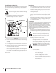
Run the engine until it begins to stall. Use the
choke to keep the engine running until all fuel
in the carburetor has been exhausted.
Referring to the engine manual, drain the fuel
from the carburetor bowl.
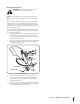
Clean the engine and the entire tractor thoroughly.3.
Fully charge the battery, then disconnect the negative
cable at the battery to prevent possible discharge.
Recharge the battery periodically when in storage.
NOTE: Remove the battery if exposed to prolonged periods
of sub-freezing temperatures. Store in a cool, dry location
where temperatures are above freezing.
Lubricate all lubrication points.5.
NOTE: We do not recommend the use of a pressure washer or
garden hose to clean your tractor. They may cause damage
to electrical components; spindles; pulleys; bearings; or the
engine. The use of water will result in shortened life and reduce
serviceability.
Removing The Tractor From Storage
Check the engine oil.
Fully charge the battery and inflate the tires to the 2.
recommended pressure.
If drained before storing, fill the fuel tank with clean, fresh 3.
gasoline.
Add clean, fresh fuel.
Start the engine and allow to idle for a few minutes to 5.
ensure engine is operating properly.
Drive the tractor without a load to make certain all the
tractor systems are functioning properly.
Adjustments
Shut the engine off, remove the
ignition key and engage the parking brake before
heavy gloves when handling the blades.
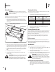
Adjusting RH & LH Drive Control Levers
and fore-and-aft for the comfort of the operator. The drive
control levers can be placed in either of two height positions,
and/or can be moved forward or rearward within the range of
the slot in each control lever mounting bracket.
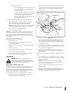
To adjust the drive control lever height, proceed as follows:
Remove the flange lock nut, flat washer, and hex screw
securing the lever to the pivot bracket.
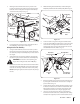
While supporting the control lever to keep it from falling, 2.
remove the hex insert flange lock nut and shoulder screw
from the bottom of the control lever and pivot bracket.
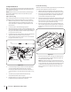
Reposition the control lever to align with the other set of 3.
holes in the pivot bracket and insert the shoulder screw
removed earlier. Fasten with the hex insert flange lock nut
and tighten until snug.
Insert the hex screw with washer through the control lever
slot and the pivot bracket. Thread the flange lock nut onto
the screw, but do not tighten now.
If you are going to adjust the control levers forward or 5.
rearward, proceed to the next step. If not, fully tighten the
flange lock nut.
To adjust the drive control levers forward or rearward, proceed as
follows:
If not already loose, loosen the flange lock nut and rotate
the control lever either forward or rearward to the desired
NOTE: If the control lever is too tight to move, slightly
loosen the hex insert flange lock nut and shoulder screw at
the bottom of the control lever.
Tighten the flange lock nut to fix the control lever in the 2.
adjusted position
Repeat the above procedure to adjust the other control 3.
lever into the same position. Adjust so that both levers are
even with each other when in the neutral position.