TRLII RILT Operator's Manu I Self Starter Mulching Mower Model 569 IMPORTANT: Read safety rules and instructions carefully before operating equipment. Warning: This unit is equipped with an internal combustion engine and should not be used on or near any unimproved forest-covered, brush-covered or grass-covered land unless the engine's exhaust system is equipped with a spark arrester meeting applicable local or state laws (if any).
TABLEOFCONTENTS Content Important Safe Operation Practices Slope Gauge Assembling Your Lawn Mower Know Your Lawn Mower Page 3 6 7 9 Operating Your Lawn Mower 10 Content Maintaining Your Lawn Mower Service & Adjustments Troubleshooting Illustrated Parts List Page 12 14 16 17 Warranty 20 FINDINGMODELNUMBER This Operator's Manual is an important part of your new lawn mower. It will help you assemble, prepare and maintain the unit for best performance. Please read and understand what it says.
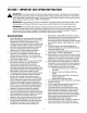
SECTION 1: IMPORTANT SAFEOPERATION PRACTICES ,_ WARNING: This and/or symbol property points out safety instructions which, notinstructions followed, could the personal safety of important yourself and others. Read and followif all in thisendanger manual before attempting to operate this machine. Failure to comply with these instructions may result in personal injury. When you see this symbol--HEED ITS WARNING.
yourfooting,releasethebladecontrolhandle 2. Do not mow slopes greater than 15 degrees as immediately andthebladewillstoprotatingwithin shown on the slope gauge. threeseconds. 3. Do not mow on wet grass. Unstable footing could 9. Mowindaylightorgoodartificiallight;walk,notrun. cause slipping. 10.Stopthebladewhencrossinggraveldrives, walkways or roads. Children 11.
9. Neverremovegascaporaddfuelwhiletheengine is hotorrunning.Allowenginetocoolatleasttwo minutesbeforerefueling. 10.Neveroverfillfueltank.Filltankto nomorethan½ inchbelowbottomoffillernecktoprovidespacefor fuelexpansion. 11.Replacegasolinecapandtightensecurely. 12. Ifgasolineisspilled,wipeitofftheengineand equipment. Moveunittoanotherarea.Wait5 minutesbeforestartingtheengine. 13.
'ql SIGHT I _;, " _l, _ ,,,, uq ! --... I HOLD THIS LEVEL A POWER POLE A CORNER ! q _ _ AND ' I _1 . WITH A VERTICAL TREE OF A BUILDING OR A FENCE POST : ...,voo_7._,, E I " ,,,,,.,,,,,. _'LOpF @ zO 15 ° L "o "5 ° w =2 _ & WARNING Do not mow on inclines with a slope in excess of 15 degrees (a rise of approximately 2-1/2 feet every 10 feet). A riding mower could overturn and cause serious injury.
SECTION3: ASSEMBLING YOURLAWNMOWER ToolsRequired , Pair of Pliers Funnel While holding the drive control bar, hook the "Z" end of the drive cable into the bottom hole of the drive control bar from inside to outside. See Figure 3. NOTE: Reference to right or left hand side of the mower and/or front or behind the mower is observed from the Drive Control Bar operating position. HardwarePack Please identify each piece of the hardware pack as shown in figure here. Wing Nut(2) e AssemblingHandle 1.
AttachingDriveAdjusterBlock Grass Catcher Insert frame The drive adjuster block is attached to the drive cable. 1. 2. 3. Remove bolt attached to the lower left handle. Align the drive adjuster block with hole in handle. Its curved side goes against the handle, Secure drive adjuster block with the bolt previously removed. See Figure 5.
ConvertingToMulcher 1. Lift the rear discharge door on the mower and lift the grass catcher up. Release the discharge door to allow it to close the rear opening of the mower. /Mulching Hinge Pin.. ConvertingToSideDischarge 1. 2. 3. 4. Make sure the grass catcher is off the unit and the rear discharge door is closed. Refer to Figure 9. On the side of the mower, lift the mulching plug. See Figure 9. Slide the two hooks of the side-discharge chute under the hinge pin on the mulching plug assembly.
CuttingHeightAdjustmentLever Start ControlLever These levers are located on each wheel and they are used to adjust the cutting height. All four levers have to be at the same relative position to ensure uniform cut. The start control lever is located on the upper right side of the upper handle. See Figure 10. The start control lever must be depressed fully while pulling the blade control bar toward upper handle for the engine to start.
To De-EnergizeSelfStarter _, the de-energizedNEVER mode, assume even if the key is is in WARNING: starter in the locked position and or removed from the engine. ALWAYS de-energize starter prior to performing any maintenance or service to the engine and or mower. Follow instructions on the engine and or machine to de-energize starter. _ Blade Remove spark plug wire from spark plug. Turn safety key to RUN position (1/4 turn clockwise).
_WARNING: BaggingGrassClippings If the mower strikes a foreign You can use the grass catcher bag to collect clippings while you are operating the mower. object, stop the engine. Remove spark plug wire from the spark plug and thoroughly inspect for any damage. Repair the damage promptly before restarting and operating the mower. Attach grass catcher following instructions on page 8. Grass clippings will automatically collect in the bag as you run the mower. Operate the mower till the grass bag is full.
Lubrication _ WARNING: When or removing the cutting blade for sharpening replacement, protect hands by using heavy gloves or a thick rag to grasp the cutting blade. 3. Remove the hex bolt which holds the blade 4. adapter-pulley assembly to the engine crankshaft. See Figure 13. Remove the pulley assembly and the bell support from the crankshaft. Remove blade from the blade adapter and pulley. be Adapter-Pulley Assembly Blad_ Blade Bell Support Hex Bolt Figure 13 5. Figure 12: Lubrication Chart 6.
SECTION7: SERVICE& ADJUSTMENTS WARNING: Be sure to disconnect the _b spark plug wire and de-energize starter before performing any repairs or maintenance. DO NOT attempt any maintenance or service to the engine and or mower equipped with the safety key in the unlocked and or energized mode. WARNING: WARNING: Use a thick piece of rag to handle the blade while sliding the belt in the next step. Make sure the engine does not start at all while doing this job. 9.
4, 5. Remove the carriage bolts and wing nuts from the handle brackets. Press out on the legs of the lower handle. Remove lower handle from the mower. Turn the lower handle around so the notch on the bottom shown bottom handle AdjustingCarburetor If the engine is running rough, minor adjustments to the carburetor may be required to compensate for differences in fuel, temperature, altitude and load. of the lower handle is facing forward as in Figure 17.
WARNING: NEVER assume starter is de- energized, even if the key is in the locked position and or removed from the engine. ALWAYS de-energize starter prior to performing any maintenance or service to the engine and or mower. Follow instructions on the engine and or machine to de-energize starter. Mower Clean underside of the mower following instructions on page 12. Lubricate mower as instructed on page 13. You can fold your mower's handle for convenient storage: 1.
SECTION10: PARTSLISTFORMODELF569 Ref No. 15, 17 25 17 Part No. Description 1. 712-0896 Lock Nut 2. 782-7598 Belt Keeper 3. 741-0124 Ball Bearing 4. 750-1050 5. 712-3025 Flange Bearing Hex Jam Nut 5/16-24 6. 736-0425 Bell Washer.325 x.930 x.45 7. 656-0047 Pulley, 3.82 x.313 x.68 8. 736-0406 Flat Washer.422 x 1.38 x.060 9. 682-0029 Front Idler Assembly 10. 732-04001 Extension Spring 11. 741-0682A Bearing Sleeve 12. 736-0570 FI-Wash.865 x 1.145 x.030 13.
ModelF569 12 11 52 65 38 79 36 44 NOTE: For painted parts, please refer to the list of color codes below. Please add IMPORTANT: For a proper working machine, use Factory Approved Parts. V-BELTS are specially designed to engage and disengage safely. A substitute (non OEM) V-Belt can be dangerous by not disengaging completely. 18 the applicable color code, wherever needed, to the part number to order a replacement part.
ModelF569 Re& No 1. 2. 3. 4. 5. 6. 7. 8. 9. 10. 11. 12. 13. 14. 15. 16. 17. 18. 19. 20. 21. 22. 23. 24. 25. 26. 27. 28. 29. 30. 31. 32. 33. 34. 35. 36. 37. 38. 39. 40. 41. 42. 44. 45. 47. 48. 49. PaN No.
MANUFACTURER'S LIMITED WARRANTY O The limited warranty set forth below is given by Troy-Bilt LLC with respect to new merchandise purchased and used in the United States, its possessions and territories. "Troy-Bilt" warrants this product against defects in material and workmanship for a period of two (2) years commencing on the date of original purchase and will, at its option, repair or replace, free of charge, any part found to be defective in materials or workmanship.