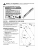
OPERATOR'S MANUAL Yard Vacuum \ Chi pper/Shredder/ Vacuum/Hose \ \ Model Number 24A-060F063 IMPORTANT: READ SAFETY RULES AND INSTRUCTIONS CAREFULLY Warning: This unit is equipped with an internal combustion engine and should not be used on or near any unimproved forestcovered, brush-covered or grass-covered land unless the engine's exhaust system is equipped with a spark attester meeting applicable local or state laws (if any).
TABLEOFCONTENTS Content Page Important Safe Operation Practices ................................................................... 3 Assembling Your Yard Vacuum ......................................................................... 5 Know Your Yard Vacuum ................................................................................... 7 Operating Your Yard Vacuum ............................................................................ 8 Maintaining Your Yard Vacuum .....................
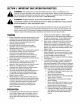
SECTION1: IMPORTANTSAFEOPERATION PRACTICES WARNING: This symbol points out important safety instructions which, if not followed, could endanger the personal safety and/or property of yourself and others. Read and follow all instructions in this manual before attempting to operate this machine. Failure to comply with these instructions may result in personal injury. When you see this symbol - heed its warning.
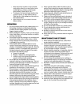
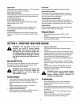
i. Neverstorethemachineor fuelcontainer insidewherethereis anopenflame,spark, or pilotlight(e.g.furnace,waterheater, spaceheater,clothesdryer,etc.) j. Toreducea firehazard,keepmachinefree ofgrass,leaves,or otherdebrisbuild-up. Cleanupoilorfuelspillageandremoveany fuelsoakeddebris. k. Allowmachine tocoolatleast5 minutes beforestoring. 9. 10. 11. 12. OPERATION 1. 2. 3. 4. 5. 6. 7. 8. Do not put hands and feet near rotating parts or in the feeding chambers and discharge opening.
,_ understand the warnings and instructions in this manual and of onthis the power machine. WARNINGand -follow YOUR RESPONSIBILITY: Restrict the use machine to persons who read, ,' ,,," 0i_ '_%. ,,.... _'_ /.... SECTION2: ASSEMBLING YOURYARDVACUUM IMPORTANT: This unit is shipped without gasoline or oil in the engine. Be certain to service engine with gasoline and oil as instructed in the separate engine manual before operating your machine.
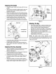
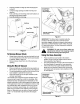
AttachingTheHandle • • • • • Unfold the upper handle until it aligns with the lower handle. Secure the two handles by tightening the wing nuts (carriage bolts must be seated properly into the handle). See Figure 1 Remove the hairpin clips from the handle brackets on the Yard Vacuum and remove the carriage bolts and wing nuts from the lower handle. See Figure 2. Place the bottom holes in lower handle over pins on handle brackets and secure with hairpin clips.
AttachingTheBlowerChute(IfEquipped) • • • Blower _Chute Grasp blower chute with one hand and slide locking rod on mounting bracket with other hand toward engine. Use end of mounting bracket as leverage when sliding the locking rod. See Figure 5. Slip blower chute over rim of the discharge opening and release locking rod to secure chute in place. Make sure the safety switch button is fully depressed by the front tab on the blower chute.
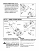
Chipper Chute HoseHandle Allow twigs and small branches up to 1 1/2" in diameter to be fed into the impeller for chipping. Used to guide hose assembly when vacuuming. Blower Chute(if Equipped) When attached to unit the blower chute is used to blow or scatter yard waste such as leaves, pine needles, or small twigs across yard. The nozzle/hose vac handle is located on top of the nozzle and it is used to regulate the vacuum between the nozzle and the hose assembly.
• • • Holdbaghandleandbagclipwhileemptyingthe contents. Compress bagopeningandfoldinnerflapover opening. Foldouterflapoverinnerflapandinsertbuttonson thebagthroughmetaloutlets. Twistthebuttonsto lockbag. Nozzle/Hose Vac Handle (Top Position) 3u_ons Bag Inner Flap Spring Loaded Pin (First Hole) Bag Handle J Outer Flap_ Figure 8 IMPORTANT: The flail screen is located inside the housing in the discharge area.
NozzleHeightAdjustment The nozzle can be adjusted to any six positions, ranging from 5/8" to 4 1/8" ground clearance. The nozzle height has to be adjusted according to the conditions. Move the height adjustment levers forward or backward to adjust the nozzle upwards or downwards. See Figure 10. NOTE: In general, raise the nozzle height to vacuum a thick layer of lea ves or to operate with the blower chute and lower the nozzle height for smoother surfaces.
Maintenance Engine Refer to the separate engine manual for all engine maintenance instructions. • • • Check engine oil level before each use as instructed in the separate engine manual packed with your unit. Read and follow instructions carefully. Clean air cleaner every 25 hours under normal conditions or once a season. Clean every few hours under extremely dusty conditions. To service the air cleaner, refer to the separate engine manual packed with your unit.
• Housing • Screws\ • • • • Lower Housing Screws • Screws Apply lubricant to the threads of impeller removal tool and then thread the tool into the crankshaft. Stop when the impeller assembly can move on the crankshaft. Remove the impeller assembly from the crankshaft. Unthread the impeller removal tool from the impeller assembly. Remove the blade using a 3/16" allen wrench on the outside of the blade and 1/2" wrench on the impeller assembly. Replace or sharpen chipper blade.
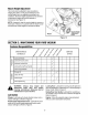
SECTION6: TROUBLESHOOTING Problem Engine fails to start Cause 1. 2. 3. Connect wire to spark plug. Fill tank with clean, fresh gasoline. Move throttle lever to FAST position. 4. 5. 6. Spark plug wire disconnected. Fuel tank empty or stale fuel. Throttle control lever not in correct starting position. (If Equipped) Choke not in CHOKE position. Blocked fuel line. Faulty spark plug. 4. 5. 6. Move choke to CHOKE position. Clean fuel line. Clean, adjust gap, or replace. 1. 2. Spark plug wire loose.
Model24A-O60F063 17 5_ _o Y 13 12 7 15 16__ 22 48 33 47 46 31 t 30 45 49 _ ) 50_ 42 40 11 39 52 _.
Model24A-O60F063 Ref. No. Part No. Ref. No. Part Description Part No. Part Description 1. 712-0161 Hex Lock Nut #10 - 24 29. 710-3025 2. 749-0438D 3. 720-0279 Upper Handle Knob 30. 31. 710-0502A 710-0751 4. 712-3004A Flange Lock Nut 5/16-18 32. 731-2484 Hose Base Adapter 5. 710-1205 Eye Bolt 33. 716-0104 E Ring .500 Dia 6. 781-1056 Upper Handle Bracket 34. 732-3035 7. 710-0528 8. 720-0314 Hex Cap Screw 5/16-18 x 1.25 Handle Knob 5/16-18 35. 36.
Model24A-O60F063 58 1 59 2 3 4 5 60 6 7_ 14 "6 23 17 _18 _21 r _.dr_ _ _ 37 5 _ _22217 . q 41 44 43 38 __34 :40 46 49 _ \24 45 35 42 53 51 42 39 44 48 50 52 '54 16 55
Model24A-O60F063 Ref. No. Part No. Ref. No. Part Description 1. 664-0095 Bag Assembly 2. 3. 681-0154 710-1054 Screen Assembly Hex Screw 5/16-24 x 1.0 4. 781-0490 5. Part No. Part Description 32. 732-1150 33. 34. 731-2294 711-1582 Chipper Blade 35. 781-0725A Front Wheel Support Brace 681-0152 Impeller Assembly 36. Rear Wheel Support Brace 6. 781-0735 37. 7. 719-0329 Pin Clip Flail Blade 781-0777 681-0155 8. 9. 715-0166 711-1401 Spiral Pin 10.
Notes 18
MANUFACTURER'S LIMITED WARRANTY TRilI RILT The limited warranty set forth below is given by Troy-Bilt LLC with respect to new merchandise purchased and used in the United States, its possessions and territories. Troy-Bilt LLC warrants this product against defects for a period of two (2) years commencing on the date of original purchase and will, at its option, repair or replace, free of charge, any part found to be defective in materials or workmanship.