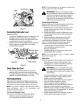
0 T RoKRILT Operator's Manu I Storm Snow Thrower Models 7524 & 8526 IMPORTANT: Warning: Read safety rules and instructions This unit is equipped with an internal combustion carefully before operating engine and should not be used on or near any unimproved covered, brush-covered or grass-covered Iand unless the engine's exhaust system is equipped with applicable local or state laws (if any).
TABLEOFCONTENTS Content Page Important Safe Operation Practices ................................................................................... 3 Assembling Your Snow Thrower ........................................................................................ 5 Know Your Snow Thrower ................................................................................................. 7 Operating Your Snow Thrower ...................................................................................
SECTION1: IMPORTANT SAFEOPERATION PRACTICES WARNING: This symbol points out important safety instructions which, if not followed, could endanger the personal safety and/or property of yourself and others. Read and follow all instructions in this manual before attempting to operate this machine. Failure to comply with these instructions may result in personal injury. When you see this symbol--heed its warning.
5. Never runanengine indoors orinapoorly ventilated area.Engine exhaust contains carbon monoxide, an odorless anddeadly gas. 6. Donotoperate machine whileunder theinfluence of alcohol ordrugs. 7. Muffler andengine become hotand can cause a burn. Do 8. 9. 10. 11. 12. 13. 14. 15. 16. 17. 18. 19. 20. not touch. Exercise extreme caution when operating on or crossing gravel surfaces. Stay alert for hidden hazards or traffic. Exercise caution when changing direction and while operating on slopes.
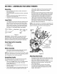
SECTION2: ASSEMBLING YOURSNOWTHROWER Unpacking Remove staples from the top, sides, and ends of the shipping crate. Set panels aside to avoid tire punctures or personal injury. Remove and discard plastic bag that covers unit. Roll the unit out of the crate. Check the crate for loose parts before discarding. LooseParts The augers are secured to the auger shaft with two shear bolts and hex lock nuts. If you hit a foreign object or ice jam, the snow thrower is designed so that the bolts may shear.
NOTE: If the tire pressure is not equal in all tires, the unit may pull to one side or the other. Cable Guide _ WARNING: Maximum tireEqual pressure under any circumstance is 30 psi. tire pressure should be maintained at all times. Excessive pressure (over 30 psi) when seating beads may cause tire/rim assembly to burst with force sufficient to cause serious injury. Traction Control & Shift Lever Move the shift lever into sixth (6) position. Perform following test to check for proper adjustment: 1.
IMPORTANT:If theaugershowsanysignsofrotating, immediately returntotheoperator'spositionandshut offtheengine.Waitforallmovingpartstostopbefore readjusting theaugercontrolcable. Toreadjustthecontrolcable,loosenthehexjam nutontheaugercontrolcable"Z"fitting. Rotatethecouplingendofthecable counterclockwise toprovidemoreslack. Retighten thehexjamnut.SeeFigure5. RepeatAugerControlTesttoverifyadjustment.
IMPORTANT: Alwaysreleasethetractioncontrolbefore changingspeeds. Auger Control The auger control is located handle. Squeeze the auger engage the augers; release disengage. Traction control be released in order to stop changed by adjusting the angle of the chute assembly. Move chute tilt control forward to decrease distance, and toward the rear to increase distance. on the left control to to must also the auger.
Makecertaintheaugeranddriveclutchleversare inthedisengaged (released) position. Movethrottlecontrolupto FASTposition. Insertignitionkeyintoslot.Becertainitsnapsinto place.Donotturn key. NOTE:Engine will not start unless ignition key is inserted into ignition slot in carburetor cover. ElectricStarter Determine that your house wiring is a three-wire grounded system. Ask a licensed electrician if you are not certain.
d_lb Use the shovel-shaped end of the clean-out tool to remove any snow and ice in the discharge chute. Re-fasten the clean-out tool to the mounting clip on the rear of the auger housing and restart engine. While standing in the operator's position (behind the snow thrower), engage the auger clutch lever for a few seconds to clear any remaining snow or ice from the discharge chute before continuing to clear snow. WARNING: The temperature of the muffler and the surrounding areas may exceed 150°F.
Skid Shoe Tip the snow thrower forward, allowing it to rest on the auger housing. See Figure g. Frame Cover The space between the shave plate and the ground can be adjusted by raising or lowering the skid shoes. For close snow removal, as when using concrete or asphalt driveway, place the the low position. Use the middle or high skid shoes when the area to be cleared on a smooth skid shoes in position for the is uneven. When operating on gravel, always put skid shoes in the high position. See Figure 11.
SECTION6: MAINTAINING YOURSNOWTHROWER Vent WARNING: Before lubricating, repairing, or inspecting, disengage all clutch levers and stop engine. Wait until all moving parts have come to a complete stop. Disconnect the spark plug wire and ground it against the engine to prevent unintended starting. GeneralRecommendations Always observe safety rules when performing any maintenance. The warranty on this snow thrower does not cover items that have been subjected to operator abuse or negligence.
excessive wear, cracks, or loose fit on the friction wheel drive hub. Also engage the traction control and check if the friction wheel is making contact with friction plate. Refer to Figure 10. If it does not make contact, adjust the traction drive cable and recheck the friction wheel. e Panel Replace friction wheel rubber if necessary. Refer to instructions on page 15. DriveBelts Contr£1 Rods _ ____Lube Check the condition of the drive belts every 50 hours of operation.
To remove the shave plate, remove the carriage bolts, belleville washers and hex nuts which attach the shave plate to the snow thrower housing.See Figure 15. Reassemble the new shave plate, with heads of carriage bolts to the inside of the housing. Tighten securely. Friction Wheel Suppo_ BeltReplacement Auger Belts Belt NOTE: It is necessary to remove both auger belts in order to change either one. If changing just one belt, be certain to check the condition of the other belt.
Lightly tap the hex nut to dislodge the ball bearing from the right side of frame. Remove the hex nut and bell washer from left end of shaft. ChangingFrictionWheelRubber The rubber on the friction wheel is subject to wear and should be checked after 25 hours of operation, and periodically thereafter. Replace the friction wheel rubber if any signs of wear or cracking are found. Slide the gear shaft to the right and slide the friction wheel assembly from the shaft.
SECTION9: TROUBLESHOOTING Problem Cause Remedy Engine fails to start. 1. 2. 3. 4. 5. 6. 7. Fuel tank empty, or stale fuel. Blocked fuel line. Choke not in ON position Faulty spark plug. Safety key not in ignition switch on engine. Spark plug wire disconnected. Primer button not being used properly. 1. 2. 3. 4. 5. 6. 7. Fill tank with fresh gasoline. Clean the fuel line. Move switch to ON position Clean, adjust gap or replace. Insert the key fully into the switch. Connect spark plug wire.
SECTION10: PARTSLISTFORMODELSSTORM7524 & STORM8526 2O 2 4O 3 12 13 39 Ref. No. 1. 2. 3. 4, 5. 6, 7. 8. 9. 10. 11. 12. 13. 14. 15. 16. 17. 18. 19. 20. 21. Part No. 731-2635 731-2643 684-04002 684-04001 736-0188 605-5193A 605-5189A 741-0493A 741-0245 784-0399 712-0429 712-3010 736-0242 05931A 684-0065 795-5226 710-0451 710-0459A 710-0726 710-0703 710-0890A 712-0116 712-3027 Part Description Mount, Chute Clean-out Tool Chute Clean-out Tool Ref. No Part No. 22. 712-0798 23.
ModelsStorm7524 & Storm8526 20 39 38 Drive Clutch Cable 5 37 13 Auger Clutch Cable 4 7 6 3 J 3O 14 26 25 9 10 28 8 I 4 1 11 5 Auger Clutch Cable 35 I I I 1 18 1
ModelsStorm7524 & Storm8526 Ref. No 1 2 3 4 5 6 7 8 9 10 11 12 13 14 15 16 17 18 19 20 21 22 23 24 PaN No. 710-1652 784-5688 784-5687A 756-0625 738-0924 784-5630B 741-0563 736-0105 712-0116 741-0598 736-0188 784-5689A 710-0538A 736-0242 714-0474 736-0160 710-0809 784-5590 784-5638 710-1652 736-0351 717-1445 714-0126 717-04094 Ref. No. Part Description TT Screw, 1/4-20 x .
ModelsStorm7524 & Storm8526 7 6 45 20 43 13 13 2O
ModelsStorm7524 & Storm8526 Ref. No. Part No. 1. 2. 3. 4. 5. 6. 731-04067 731-04059 710-1003 725-1672 747-1136 725-1658 7. 8. 9. 10. 11. 12. 13. 14. 15. 629-0059 726-0100 720-0201A 747-0737 684-0053B 736-0185 714-0104 741-0475 705-5266 16. 17. 18. 19. 20. 21. 22. 23. 736-0270 712-0287 736-0275 736-0119 710-0643 710-0788 684-0008A 747-0621 Ref. No. Part Description Handle Panel (8526) Handle Panel (7524) Special B Screw (8526) Lens Assembly (8526) Lamp Retainer (8526) Halogen Lamp (8526) 24.
ModelsStorm7524 & Storm8526 31 14 22 / 15 6 18 26 23 Ref. No, 1. 2. 3. 4. 5. 6. 7. 8. 9. 10. 11. 12. 13. 14. 15. 16. 17. Part No. 05896A 710-1245B 710-0230 710-0627 710-0654A 710-0696 710-1652 710-3005 712-0181 731-1324 732-0710 736-0242 736-0247 736-0270 736-0331 736-0505 748*0234 Description Idler Brkt. Hex Hd. Cap Screw 5116-24 Thd. Hex Hd. Cap Screw 114-28 Thd. Hex Hd. Cap Screw 5116-24 Thd. TT_Tap Screw 3/8-16 Thd. Hex Hd. Screw 3/8_24 TT_Tap Screw 1/4-20 Thd. Hex Hd. Cap Screw 318-16 Thd.
ModelsStorm7524 & Storm8526 i ,,.........I 39 33 Ref. No. 22 1. 2. 3, 4. 6 5. 6. 7. 8. 9. 10. 11. 12. 13. 15. 16. 17. 18. 19. 10 20. 21. 16 22. 23, 24. 25. 26. 27. 28, 29. 30. 31. 32. 33, 34. 35. 36. 37. 38. 39. 40. 41. 42. 43. 23 Part No, 710-04071 710-0262 710-0805 710-0895 710-3015 712-0429 712-3027 731-04427 731-0851A 731-1313C 731-1300B 784-5680 736-0159 736-0506 746-0896 746-0901 784-5594 784-5604 Description Carriage Screw Carriage Bolt 5/16-18 x 1.75" Hex Bolt 5/16-18 x 1.
ModelStorm7524 17 12 \ 10 13 9 1,1 \ 8 18 R_. No. 1. 2. 3. 4. 5. 6. 7. 8. 9. 10. 11. 12. 13. 14. 15. 16. 17. 18. 13 Part No, 618-0414A 618-0123 618-0418 710-0642 711-0908A 714-0161 715-0143 717-0526 717-0528 718-0186 721-0325 721-0327 736-0351 736-0369 736-0445 737-3000 741-0662 741-0663 Description Auger Gearbox Ass'y Comp. Housing Assembly, RH Housing Assembly, LH Screw, 1/4-20 x .75 24" Auger Axle Hi-Pro Key Spirol Pin Worm Shaft .75 O.D. Worm Gear 20T Thrust .75 I.D. x .415 O.D.
ModelStorm8526 17 15 10 13 X 14 1. 2. 3. 4. 5. 6. 7. 8. 9. 10. 11. 12. 13. 14. 15. 16. 17. 18. 5 13 Part No, 618-0415A 618-0123 618-0418 710-0642 711-0909A 714-0161 715-0143 717-0526 717-0528A 718-0186 721-0325 721-0327 736-0351 736-0369 736-0445 737-3000 741-0662 741-0663 \ t 8 18 Ref. No. 9 \ 12 Description Auger Gearbox Ass'y Comp. Housing Assembly, RH Housing Assembly, LH Screw, 1/4-20 x .75 26" Auger Axle Hi-Pro Key Spirol Pin Worm Shaft .75 Worm Gear 20T Thrust .75 x .415 Plug 1/4 x .
MANUFACTURER'S LIMITED WARRANTY FOR: 0 TPD RILT'__ _ The limited warranty set forth below is given by Troy-Bilt LLC with respect to new merchandise purchased and used in the United States, its possessions and territories. "Troy-Bilt" warrants this product against defects in material and workmanship for a period of two (2) years commencing on the date of original purchase and will, at its option, repair or replace, free of charge, any part found to be defective in materials or workmanship.