® Operator's Manual Snow Thrower Model 521mSquall IMPORTANT: Read safety rules and instructions carefully before operating equipment. Warning: This unit is equipped with an internal combustion engine and should not be used on or near any unimproved forest-covered, brushcovered or grass-covered land unless the engine's exhaust system is equipped with a spark arrester meeting applicable local or state laws (if any).
TABLEOFCONTENTS Content Page 3 5 6 7 8 Important Safe Operation Practices Assembling Your Snow Thrower Know Your Snow Thrower Operating Your Snow Thrower Making Adjustments Content Maintaining Your Snow Thrower Troubleshooting Illustrated Parts List Warranty Page 9 11 12 Back Cover FINDINGMODELNUMBER This Operator's Manual is an important part of your new snow thrower. It will help you assemble, prepare and maintain the unit for best performance. Please read and understand what it says.
SECTION1: IMPORTANT SAFEOPERATION PRACTICES ,_ WARNING: This and/or symbol property points out important and safety instructions which, notinstructions followed, could the personal safety of yourself others. Read and followif all in thisendanger manual before attempting to operate this machine. Failure to comply with these instructions may result in personal injury. When you see this symbol--heed its warning.
area•Engine exhaust contains carbon monoxide, an Maintenance& Storage odorless anddeadly gas. 1. Never tamper with safety devices• Check their proper 6. Donotoperate machine whileundertheinfluence of operation regularly• alcohol ordrugs• 2. Disengage the control bail and stop engine• Wait until the 7. Mufflerandenginebecomehotandcancauseaburn. Do auger/impeller come to a complete stop. Disconnect the nottouch• spark plug wire and ground against the engine to prevent 8.
SECTION2: ASSEMBLING YOURSNOWTHROWER NOTE: All references to left or right side of the snow thrower is from the operating position only. • • RaisingUpperHandle • Loosen the hand knob on each side of the handle. Remove packing material, if any. • Remove the wing knob, flat washer and carriage bolt from the lower chute. See Figure 2. Pivot the upper chute upward over the lip on the lower chute so that there is NO gap between the upper chute and the lower chute. See Figure 2.
SECTION3: KNOWYOURSNOWTHROWER _ stop ARNING: the machine Beand familiar disengage with all them the controls quickly.on the snow thrower and their proper operation. Know how to er Control Handle Recoil Starter Gasoline Cap Starter Button Access Chute Assem__ _Oil Fill Lever Choke Auger S_ahavi Pla_tt__ Figure 3 AugerControl Handle Located on the upper handle, the auger control handle is used to engage and disengage the auger. The snow thrower is designed to propel by the rotation of the auger.
SECTION4: OPERATING YOURSNOWTHROWER BeforeStarting • _ instructions ARNING:andRead, warnings understand, on the machine and follow and all in this manual before operating. • • The spark plug wire was disconnected for safety. Attach spark plug wire to spark plug before starting. • GasandOilFill-Up • • Check oil and gasoline level and add if necessary. Follow related instructions in the separate engine manual packed with your snow thrower.
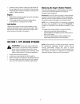
ToStopEngine • • To stop engine, turn ignition key counter-clockwise. Disconnect the spark plug wire from the spark plug to prevent accidental starting while equipment is unattended. To help prevent possible freeze-up of starter, proceed as follows: • • • • Position the chute assembly opening by using the Chute Handle to throw the snow in the desired direction. See Figure 5. Wing Chute Run engine for a few minutes before stopping to help dry off any moisture on the engine.
To adjust, tip the snow thrower back so that it rests on the handle. Loosen the four lock nuts and bolts which secure the shave plate to the housing. See Figure 7. Move the shave plate to desired position and retighten the nuts and bolts securely. If the auger seems to hesitate when rotating while the engine maintains a constant speed, an adjustment is necessary. Proceed as follows: The upper hole in the control handle provides for an adjustment in cable tension.
• • Installnewshaveplate,makingsuretheheadsof thecarriageboltsareontheinsideofthehousing. Adjusttheshaveplateaccording toinstructions on page8.Tightensecurely. ReplacingtheAuger'sRubberPaddles The snow thrower auger's rubber paddles are subject to wear and should be replaced if any signs of excessive wear is present. Engine • • IMPORTANT: Do NOT allow the auger's rubber paddles to wear to the point where portions of the metal auger itself can come in contact with the pavement.
SECTION8: TROUBLESHOOTING GUIDE Problem Engine fails to start Cause Remedy 1. 2. Fuel tank empty, or stale fuel Blocked fuel line 1. 2. Fill tank with clean fresh gasoline. Clean fuel line 3. 4. 5. 6. Key not in ON position Spark plug wire disconnected Faulty spark plug Engine not primed 3. 4. 5. 7. Engine flooded from excessive priming Insert key and turn to ON position Connect wire to spark plug. Clean spark plug, readjust gap, or replace. Prime engine four times.
SECTION9: PARTSLIST 32 38 35 _35 46 24 45 12 26 5O 47 12 43 8/ 18 42 14 37 11 18 16 28 22 / 27 30 22 l'\o t 12 28 13 J 15 19 17 13 12 9 9
Model521 REE NO. 1 2 3 4 5 6 7 8 9 10 11 12 13 14 15 16 17 18 19 20 21 22 23 24 25 26 27 28 29 30 31 32 33 34 35 36 37 38 39 40 41 42 43 44 45 46 47 48 49 50 51 PART NO.
Model521 REE NO. 1 2 3 4 5 6 7 8 9 10 11 PART NO. 710-04071 710-0451 712-04063 720-0284 731-04127 731-04353 731-04886 731-04388 731-04426 732-04111 736-0159 DESCRIPTION Carriage Screw, 5/16-18 x 1.0 Carriage Bolt, 5/16-18 x.075 GR 1 Hex Flange Lock Nut, 5/16-18, Gr. 5 Handle Knob Assembly 5/16-18 Lower Chute 5" Dia Ring-Lower Chute Chute, Adapter 5" Dia Handle-Chute 5" Dia Upper Chute Chute Adjustment Spring Flat Washer,.349 ID x .879 OD x .
Model521 18 24 5 19 \ 7 8 6 13 3 21 21 14 23 4 22 20 REE NO. 1 2 3 4 5 6 7 8 9 10 12 13 14 15 16 17 18 19 2O 21 22 23 24 25 PART NO. 629-0071 710-0627 710-0409 710-0654A 710-0896 710-1003 7511152847 750-04297 726-0205 726-0470 731-2825 736-0119 736-0149 7512B1476 747-04169 751-0535 751-10049 751-10023 751-0101A 756-0416B 756-0475 790-00047 790-00134 726-0201 DESCRIPTION Extension Cord Hex Screw, 5/16-24 x .75 Hex Screw, 5/16-24 x 1.75 Self Tapping Screw, 3/8-16 x 1.00 Hex Screw, 1/4-20 x .
MANUFACTURER'S LIMITED WARRANTY FOR: ® m The limited warranty set forth below is given by Troy-Bilt LLC with respect to new merchandise purchased and used in the United States and/or its territories and possessions, and by MTD Products Limited with respect to new merchandise purchased and used in Canada and/or its territories and possessions (either entity respectively, "Troy-Bilff).