v® Operator's Manual 2-Cycle Gasoline Trimmer Model TB70SS IMPORTANT: READ SAFETY RULES AND INSTRUCTIONS P/N 769-02173 (10/05) CAREFULLY
THANK YOU TABLE OF CONTENTS Thank you for buying this quality product. This modern outdoor power tool will provide many hours of useful service. You will find it to be a great labor-saving device. This operator's manual provides you with easy-tounderstand operating instructions. Read the whole manual and follow all the instructions to keep your new outdoor power tool in top operating condition. Service Information ......................... Rules for Safe Operation Know Your Unit .....................
The purpose of safety symbols is to attract your attention to possible dangers. The safety symbols, and their explanations, deserve your careful attention and understanding. The safety warnings do not by themselves eliminate any danger. The instructions or warnings they give are not substitutes for proper accident prevention measures. SYMBOL MEANING SAFETY ALERT: Indicates danger, warning or caution. Attention is required in order to avoid serious personal injury.
• Alwaysstoptheengineandallowittocoolbeforefilling thefueltank.Neverremove thecapofthefueltank,or addfuel,whentheengineishot.Neveroperatetheunit withoutthefuelcapsecurelyinplace.Loosenthefuel tankcapslowlyto relieveanypressure inthetank. • Mixandaddfuelina clean,well-ventilated outdoorarea wheretherearenosparksorflames.Slowlyremove the fuelcaponlyafterstoppingengine.Donotsmokewhile fuelingor mixingfuel.Wipeupanyspilledfuelfromthe unitimmediately. Alwayswipeunitdrybeforeusing. • Movetheunitatleast30feet(9.
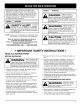
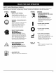
SAFETY AND INTERNATIONAL SYMBOLS This operator's manual describes safety and international symbols and pictographs that may appear on this product. Read the operator's manual for complete safety, assembly, operating and maintenance and repair information. SYMBOL MEANING SYMBOL • SAFETY ALERT SYMBOL Indicates danger, warning, or caution. May be used in conjunction with other symbols or pictographs.
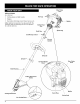
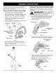
Blue Choke f APPLICATIONS Asa trimmer: • Cuttinggrassandlightweeds. • Edging • Decorative trimmingaroundtrees,fences,etc. Otheroptionalaccessories maybeusedwiththe TB70SS.Referto Operating the EZ-Link System Lever Fuel Cap Muffler Starter Rope Grip for a list of add-ons.
On some units, the D-handle may be pre-installed, requiring only loosening screws and some adjustment. If this is the case, go to step 4. INSTALLING 1. 2. AND ADJUSTING THE D-HANDLE Remove the screws and bottom clamp piece that were installed on the D-handle for shipping. Place D-handle the over the shaft housing and onto the bottom clamp (Fig. 1). Place it a minimum of 6 inches (15.24 cm) from the end of the shaft grip. 3. Start screws with a large Flat-head or T-25 Torx screwdriver.
OIL AND FUEL MIXING INSTRUCTIONS Old and/or improperly mixed fuel are the main reasons for the unit not running properly. Be sure to use fresh, clean unleaded fuel. Follow the instructions carefully for the proper fuel/oil mixture. Definition of Blended Fuels Today's fuels are often a blend of gasoline and oxygenates such as ethanol, methanol, or MTBE (ether). Alcohol-blended fuel absorbs water. As little as 1% water in the fuel can make fuel and oil separate. It forms acids when stored.
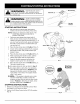
WARNING: Operate this unit only in a well- ventilated outdoor area. Carbon monoxide exhaust fumes can be lethal in a confined area. Start/On ( I) WARNING: Avoid accidental starting. Make sure you are in the starting position when pulling the starter rope (Fig. 8). To avoid serious injury, the operator and unit must be in a stable position while starting. STARTING Throttle Control Fig. 6 INSTRUCTIONS 1. Mix gas with oil. Fill fuel tank with fuel/oil mixture. See Oil and Fuel Mixing Instructions.
OPERATING The EZ-Link Add-Ons. THE EZ-LINK TM SYSTEM TM system enables the use of these optional NOTE: Aligning the release button with the guide recess will help installation (Fig. 9). Cultivator ................................ TBGC Edger ................................... TBLE Hedge Trimmer TBAH ........................... Straight Shaft Trimmer ...................... Turbo Blower ............................. TM Coupler Primary Hole TBPS ..............................
HOLDING THE TRIMMER WARNING: A, ways wear eye, hearing, foot and body protection to reduce the risk of injury when operating this unit. Before operating the unit, stand in the operating position (Fig. 12). Check for the following: • The operator is wearing eye protection and proper clothing • With a slightly-bent right arm, the operator's hand is holding the shaft grip • • • NOTE: Do not rest the Bump Head TM on the ground while the unit is running.
MAINTENANCE SCHEDULE NOTE: Maintenance, replacement, or repair of the emission control devices and system may be performed by any non-road engine repair establishment, individual or authorized service dealer. Perform these required maintenance procedures at the frequency stated in the table. These procedures should also be a part of any seasonal tune-up. NOTE: Some maintenance procedures may require special tools or skills.
For Use with Single Line ONLY For Use with SplitLine or Single Line TM 9. Insert the end of the line into the open hole in the inner reel and pull the line tight to make the loop as small as possible (Fig. 21). 10. Before winding, split the line back about 6 inches. 11. Wind the line in tight even layers in the direction indicated on the inner reel. NOTE: Failure to wind the line in the direction indicated will cause the cutting attachment to operate incorrectly. Fig.
INSTALLING A PREWOUND REEL 1. Hold the outer spool with one hand and unscrew the bump knob counterclockwise (Fig. 15). Inspect the bolt inside the bump knob to make sure it moves freely. Replace the bump knob if damaged. 2. Remove the old inner reel from the outer spool (Fig. 16). 3. Remove the spring from the old inner reel (Fig. 16). 4. Place the spring in the new inner reel. NOTE: The spring must be assembled on the inner reel before reassembling the cutting attachment. 5.
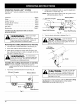
SPARK ARRESTOR CARBURETOR MAINTENANCE ADJUSTMENT Remove air filter/muffler cover. Refer to Removing the Air Filter/Muffler Cover. The idle speed of the engine is adjustable through the air filter/muffler cover (Fig. 30). Locate the muffler, but do not remove it. Find the screw on the bottom of the muffler (Fig. 29). Remove the screw using either a torx #20 or flat blade screwdriver. NOTE: Careless adjustments can seriously damage your unit.
2. TRANSPORTING Release the throttle trigger and let the engine idle. If the engine stops, insert a small phillips or flat blade screwdriver into the hole in the air filter/muffler cover (Fig. 30). Turn the idle speed screw in, clockwise, 1/8 of a turn at a time (as needed) until the engine idles smoothly. • Allow the engine to cool before transporting. • Drain fuel from unit. • Tighten fuel cap before transporting. NOTE: The cutting attachment should not rotate when the engine idles. 3.
CAUSE ACTION Empty fuel tank Fill fuel tank with properly mixed fuel Primer bulb wasn't pressed enough Press primer bulb fully and slowly 10 times Engine is flooded Squeeze the trigger and pull the starter rope Old or improperly mixed fuel Drain gas tank and add fresh fuel mixture Fouled spark plug Replace or clean the spark plug Plugged spark arrestor Clean or replace spark arrestor The outside temperature is below 40 ° F Pull the starter rope up to 10-15 times The outside temperature is
Engine Type .......................................................................................................................................... Air-Cooled, 2-Cycle Stroke .................................................................................................................................................... 1.25 in. (31.75 mm) Displacement ............................................................................................................................................. 1.9 cu in.
California / EPA Emission Control Warranty Statement Your Warranty Rights and Obligations The California Air Resources Board, the Environmental Protection Agency and MTD LLC (MTD) are pleased to explain the emission control system warranty on your 2005 and later small off-road engine. New small off-road engines must be designed, built and equipped to meet stringent anti-smog standards.
MANUFACTURER'S LIMITED WARRANTY FOR: TRO BI£T The limited warranty set forth below is given by Troy-Bilt LLC with respect to new merchandise purchased and used in the United States, its possessions and territories. Troy-Bilt LLC warrants this product against defects in material and workmanship for a period of two (2) years commencing on the date of original purchase and will, at its option, repair or replace, free of charge, any part found to be defective in material or workmanship.
2-CYCLE ENGINE PARTS - TB70SS GAS TRIMMER - ENGINE I L Item 1 2 3 4 5 6 7 8 9 10 11 12 13 14 15 16 17 18 19 20 21 22 23 24 25 26 27 28 29 30 31 32 E22 Part No.
BOOM AND TRIMMER PARTS - TB70SS 2 CYCLE TRIMMER ® Item 1 2 3 4 5 6 7 8 9 10 11 12 13 14 15 16 17 18 19 20 21 22 23 24 25 26 27 28 Pa_ No. 753-04234 753-04119 791-182690 791-182405 753-04405 753-04344 791-180869 791-181070 791-182167 791-182168 753-1190 791-182057 791-181617 791-181981 753-04386 753-1212 791-181166 791-153597 791-145569 791-180549 791-180547 791-180548 791-682061 791-153619 791-610660 791-610317B 753-1155 791-153066B _tional Accessories 791-180120 Replacement Line, 0.