® Operator's Manual 2-Cycle Gasoline Trimmer Model TB 7 5SS IMPORTANT: READ SAFETY RULES AND INSTRUCTIONS CAREFULLY NOTE: For users on UrnS.Forest Land and in the states of California, Maine, Oregon and Washington. All U.S.
Content Page Calling Customer Support .................................................... 2 Rules for Safe Operation .....................................................
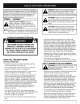
The purpose of safety symbols is to attract your attention to possible dangers. The safety symbols, and their explanations, deserve your careful attention and understanding. The safety warnings do not by themselves eliminate any danger. The instructions or warnings they give are not substitutes for proper accident prevention measures. SYMBOL MEANING IA WARNING: Failure to obey a safety warning can result in injury to yourself and others.
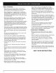
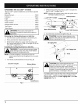
WHILE OPERATING • Never start or run the unit inside a closed room or building. Breathing exhaust fumes can kill. Operate this unit only in a well ventilated area outdoors. • Wear safety glasses or goggles that are marked as meeting ANSI Z87.1-1989 standards, and ear/hearing protection when operating this unit. Wear a face or dust mask if the operation is dusty. Long sleeve shirts are recommended. • Wear heavy, long pants, boots and gloves.
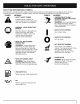
SAFETY AND INTERNATIONAL SYMBOLS This operator's manual describes safety and international symbols and pictographs that may appear on this product. Read the operator's manual for complete safety, assembly, operating and maintenance and repair information. SYMBOL MEANING SYMBOL MEANING THROWN OBJECTS AND ROTATING CUTTER CAN CAUSE SEVERE INJURY Indicates danger, warning, or • SAFETY caution. May ALERT be used SYMBOL in conjunction with other symbols or pictographs.
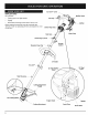
EZ-Start TM Lever _ OAPPLICATIONS As a trimmer: Muffler Guard J Cutting grass and light weeds. Fuel Cap Edging Decorative trimming around trees, fences, etc. Other optional accessories may be used with the TB75SS. Refer to Operating the EZ-Link System for a list of add-ons. Starter Rope Grip Spark Plug Shaft Grip On/Off Stop Control Throttle Control Shoulder Strap Clip D-Handle EZ-Start Lever Air Filter/Muffler Cover Shaft Housing Cutting / Line Cutting Attachment Shield / Blade \ Eng
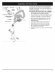
Shaft Grip (4) Screws-___ Shaft Housing On/Off Stop Control _ ! On some units, the D-handle may be preinstalled and only require loosening the screws and adjusting the D-handle to the operator. Go to step 4 for adjusting the D-handle if preinstalled. INSTALLING Remove the screws and bottom clamp piece that were installed on the D-handle for shipping. 2. Place D-handle the over the shaft housing and onto the bottom clamp (Fig. 1). Place it a minimum of 6 inches (15.
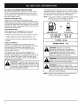
OIL AND FUEL MIXING INSTRUCTIONS Old and/or improperly mixed fuel are the main reasons for the unit not running properly. Be sure to use fresh, clean unleaded fuel. Follow the instructions carefully for the proper fuel/oil mixture. Definition of Blended Fuels Today's fuels are often a blend of gasoline and oxygenates such as ethanol, methanol, or MTBE (ether). Alcohol-blended fuel absorbs water. As little as 1% water in the fuel can make fuel and oil separate. It forms acids when stored.
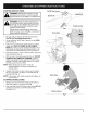
STARTING INSTRUCTIONS WARNING: Operate this unit only in a wellventilated area outdoors. Carbon monoxide exhaust fumes Can be lethal in a confined area. On/Off Stop Control Siop/Off (o) Start/On / (I) WARNING: Avoid accidental Starting. Be in the starting position when pulling the starter rope (Fig. 5). The operator and unit must be in a stable position while starting to avoid serious personal injury.
OPERATINGTHE EZ-LINW M SYSTEM 2. The EZ-Link TM system enables the use of these optional Add-Ons. Blower/Vacuum ........................... TBBV Cultivator ................................ TBGC Edger ................................... TBLE Hedge Trimmer ........................... Snow Thrower ............................ TBHS TBST Straight Shaft Trimmer ...................... Tree Pruner .............................. TBSS TBTP Turbo Blower TBTB .............................
HOLDING THE TRIMMER NOTE: Do not rest the Bump Head TM on the ground while the unit is running. and body protection to reduce the risk Of WARNING: Always wear eye, hearing, foot I njury when operat ng this un t. Before operating the unit, stand in the operating position (Fig. 9).
MAINTENANCE SCHEDULE Perform these required maintenance procedures at the frequency stated in the table. These procedures should also be a part of any seasonal tune-up. NOTE: Some maintenance procedures may require special tools or skills. If you are unsure about these procedures take your unit to any non-road engine repair establishment, individual or authorized service dealer. maintenance or repairswith unit running. Always do I maintenance and repairs on a co01unit.
. 4. Pull old line out of the line loading and line locking holes (Fig. 13 and 14). Insert a piece of trimming line into one of the two eyelets in the outer spool. Push it up through the line loading hole in the inner reel (Fig. 13). Do not bend the line when inserting it into the eyelet. 7. Repeat procedures 4-6 with the second piece of line. 8. Hold the outer spool. Wind the inner reel counterclockwise until approximately four (4) inches (102 mm) of line remain (Fig. 16).
2. Pull the old inner reel with existing line from the outer spool. 3. Insert the ends of the prewound inner reel line into the outer spool eyelets (Fig. 19). Push the new inner reel, arrow side up, into the outer spool. 4. Remove any existing line from the inner reel before cleaning. Remove any debris or grass from the knob, spring, inner reel and foam seal. Wash the inner reel with warm soapy water (Fig. 21). Inner Reel Fig. 21 5. 4. Fig.
AIR FILTER MAINTENANCE Removing the Air FUter/Muffier Cleaning the Air Filter Clean and re-oil the air filter every 10 hours of operation. It is an important item to maintain. Failure to maintain the air filter will VOID the warranty. Cover always turn your trimmer off and allow it tO WARNING: TO avoid Serious personal injury, coo before you c ean or serv ce t. 1. 2. Remove the four (4) screws securing the air filter/muffler cover (Fig. 23). Use a flat blade or T20 Torx bit screwdriver.
Reinstalling the Air Filter/Muffler 1. 2. Cover Place the air filter/muffler cover over the back of the carburetor and muffler. Align the screw holes. Spark Arrestor Insert the four (4) screws into the holes in the air filter/muffler cover (Fig. 23) and tighten. Do not over tighten. SPARK ARRESTOR \ \ \ Exhaust Gasket \ MAINTENANCE 1. Remove the air filter/muffler Air Filter/Muffler Cover. cover. See Removing the 2. Locate the muffler front and the two (2) bolts securing it to the engine.
CARBURETOR \ ADJUSTMENT The idle speed of the engine is adjustable through the air filter/muffler cover (Fig. 30). NOTE: Careless adjustments can seriously damage your unit. An authorized service dealer should make carburetor adjustments. ! Check Fuel Mixture Old and/or improperly mixed fuel is usually the reason for improper unit performance. Drain and refill the tank with flesh properly-mixed fuel prior to making any adJustments. Refer to Oil and Fuel Information.
REPLACING THESPARKPLUG LONG TERM Use a Champion RDJ7Y spark plug (or equivalent). The correct air gap is 0.020 inch (0.5 mm). Remove the plug after every 25 hours of operation and check its condition. 1. Stop the engine and allow it to cool. Grasp the plug wire firmly and pull it from the spark plug. 2. Clean around the spark plug. Remove the spark plug from the cylinder head by turning a 5/8 in. socket counterclockwise. 3. Replace a cracked, fouled or dirty spark plug. Set the air gap at 0.020 in. (0.
CAUSE Emptyfueltank Primerbulbwasn'tpressedenough Engineflooded Oldor improperly mixedfuel Fouledsparkplug Pluggedsparkarrestor EZ-Startleverwasn'tflipped CAUSE ACTION Fillfueltankwithproperlymixedfuel Pressprimerbulbfullyandslowly7-9times Usestartingprocedure(withthe EZ-Start lever TM clicked) Drain gas tank and add fresh fuel mixture Replace or clean the spark plug Clean or replace spark arrestor Flip EZ-Start lever ACTION Air filter is plugged Replace or clean the air filter Old or improperly mix
Engine Type ................................................................... Stroke ........................................................................ Displacement .................................................................... Clutch Type ........................................................................... Idle Speed RPM ................................................................. Operating RPM ...................................................................... Ignition Type ..
EPA Emission Control Warranty Statement Your Warranty Rights and Obligations The Environmental Protection Agency and MTD SOUTHWEST INC (MTD) are pleased to explain the emission control system warranty on your 2002 and later small off-road engine. New small off-road engines must be designed, built and equipped to meet stringent anti-smog standards.
ENGINE PARTS - MODEL TB75SS 2-CYCLE GAS TRIMMER PPN Item I Part No.
BOOM AND TRIMMER PARTS - MODEL 2-CYCLE GAS TRIMMER TB75SS PPN 41BDT75C063 / / ® @ d Item 1 2 3 4 5 6 7 8 9 10 11 12 13 14 15 16 17 18 19 20 21 22 23 24 25 26 27 28 29 30 31 32 33 34 35 36 Part No.
MANUFACTURER'S LIMITED WARRANTY FOR: TROI BILT" n n _mmm mmmn The limited warranty set forth below is given by Troy-BUt LLC with respect to new merchandise purchased and used in the United States, its possessions and territories. Troy-Bilt LLC warrants this product against defects in material and workmanship for a period of two (2) years commencing on the date of original purchase and will, at its option, repair or replace, free of charge, any part found to be defective in material or workmanship.