TROY:BILT ° 2-Cycle Gasoline Trimmer / Brushcutter Model TB9OBC IMPORTANT:READ SAFETY RULES AND INSTRUCTIONS CAREFULLY NOTE: For users on U.S. Forest Land and in the states of California, Maine, Oregon and Washington. AU U.S.
Content Page Calling Customer Support Rules for Safe Operation ................................................. 2 ................................................ 3 Know Your Unit ........................................................... 7 Assembly Instructions ................................................ Oil and Fuel Information .................................................... 8 12 Starting/Stopping 13 Instructions ..............................................
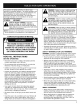
The purpose of safety symbols is to attract your attention to possible dangers. The safety symbols, and their explanations, deserve your careful attention and understanding. The safety warnings do not by themselves eliminate any danger. The instructions or warnings they give are not substitutes for proper accident prevention measures. SYMBOL DANGER: Failure to obey a safety warning will result in serious injury to yourself or to others.
• Wear heavy, long pants, boots, gloves and a long sleeve shirt. Do not wear loose clothing, jewelry, short pants, sandals or go barefoot. Secure hair above shoulder level. • The cutting attachment shield must always be in place while operating the unit. Do not operate unit without both trimming lines extended, and the proper line installed. Do not extend the trimming line beyond the length of the shield. • This unit has a clutch. The cutting attachment remains stationary when the engine is idling.
L OTHER SAFETY WARNINGS • Never douse or squirt the unit with water or any other liquid. Keep handles dry, clean and free from debris. Clean after each use see Cleaning and Storage instructions • Never store the unit, with fuel in the tank, inside a building where fumes may reach an open flame or spark. • Keep these instructions. Refer to them often and use them to instruct other users. If you loan someone this unit. also loan them these instructions.
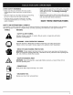
SYMBOL MEANING • OIL Refer to operator's • THROWN // manual for the proper type of oil. OBJECTS AND ROTATING CUTTER CAN CAUSE WARNING: Do not operate without the cutting attachment Keep away from the rotating cutting attachment. • ON/OFF SEVERE INJURY shield in place. STOP CONTROL ON / START / RUN • ON/OFF STOP CONTROL OFF OR STOP ° HOT SURFACE WARNING Do not touch a hot muffler, gear housing or cylinder. You may get burned. These parts get extremely hot from operation.
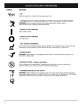
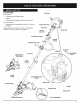
APPLICATIONS As a trimmer: Fuel Cap \\\ Cutting grass and light weeds. \\\ Edging. Decorative trimming around trees, fences, etc. As a brushcutter; Cutting weeds and light bush of up to 1/2 inch in diameter. Starter Rope Grip Shaft Grip Other optional accessories may be used with the TB90BC. See list of add-ons on page 14. Throttle Lock-C On/Off Stoic Throttle Control Shoulder Strap J-Handk EZ.Link Blade Shield / Shield Mount EZ-Start Lever Air Filter/Muffler Cover TM \\ TM \ \ Shaft Housin
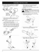
INSTALLING 1. AND ADJUSTING THE J-HANDLE 6. While holding the unit in the operating position (Fig. 3), position the J-handle to the location that provides you the best grip. 7. Tighten the clamp screws evenly, until the J-handle is secure. Place the J-handle between the top and middle clamp pieces (Fig. 1). INSTALLING THE HARNESS when using the cutting blade to avoid serious I WARNING: AlWays use thesh°ulder harness jI personal injury. Top Clamp Middle Clamp Bottom Clamp J Nuts _ 1.
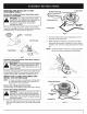
REMOVING AND INSTALLING ATTACHMENT SHIELD CUTTING Output Shaft _ Shaft Bushing Hole \, • Remove the cutting attachment shield when using the unit as a brushcutter. WARNING: The cutting attachment shield should NOT be installed when operating the unit with a blade. Remove the cutting attachment shield before removing or installing the blade. Remove the cutting attachment shield from the shield mount by removing the three (3) screws with a flat blade screwdriver (Fig. 7). Store parts for future use.
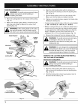
T_ Install the Cutting Blade always wear To gloves handling or injury, ARNING: avoid while serious personal installing the blade _ 4. . Place the cutting blade on the output shaft bushing (Fig. 11). 5. Make sure that the cutting blade is centered on the pilot step and sitting flat against the output shaft bushing (Fig. 12). the unit will vibrate, and the blade may fly WARNING: If the cutting blade is off-center, 1 off, which can cause serious personal injury. J ,_, Blade Retainer 7.
3. Whileholdingthe lockingrod,loosenthenuton thebladebyturningit clockwisewitha 5/8inch closed-endor socketwrench(Fig.14). 4. Removethenut,bladeretainer,andblade.Storethe nutandbladetogetherforfutureuseina secure place.Storeoutof reachof children. Installthe Cutting Attachment 5. Align the shaft bushing hole with the locking rod slot and insert the locking rod into the shaft bushing hole. (Fig. 8, Pg. 9).
OIL AND FUEL MIXING INSTRUCTIONS Old and/or improperly mixed fuel are the main reasons for the unit not running properly. Be sure to use fresh, clean unleaded fuel. Follow the instructions carefully for the proper fuel/oil mixture. Definition of Blended Fuels Today's fuels are often a blend of gasoline and oxygenates such as ethanol, methanol or MTBE (ether). Alcohol-blended fuel absorbs water. As little as 1% water in the fuel can make fuel and oil separate. It forms acids when stored.
STARTING [_, INSTRUCTIONS ventilated area outdoors. Carbon monoxide exhaust fumes can bethis lethal a confined WARNING: Operate unitinonly in a well-area. WARNING: Avoid accidental starting. Be in the starting position when pulling the starter rope (Fig. 9). The operator and unit must be in a stable position while starting to avoid serious personal injury. Avoid serious personal injury, ensure any Add-On being used is installed correctly and secure before starting unit. 1. Mix gas with oil.
OPERATING THE EZ-LINK TM SYSTEM 2. The EZ-Link TM system enables the use of these optional add-ons. Blower/Vacuum .......................... Cultivator ............................... BV720r GC720r Edger .................................. Hedge Trimmer .......................... Snow Thrower ........................... LE720r HS720r ST720r Straight Shaft Trimmer ..................... Sweeper/Blower .......................... Tree Pruner .............................. Turbo Blower ..................
L 1 HOLDING I,_ THE TRIMMER body protection and strap to reduce the risk Always wear this eye,unit. hearing, foot, of ARNING: injury when operating Before operating the unit, stand in the operating position (Fig. 22). Check for the following: The operator is wearing eye protection and proper clothing. The right arm is slightly bent, and the hand is holding the shaft grip. Each time the head is bumped, about 1 inch (25.4 ram.) of trimming line is released.
DECORATIVE TRIMMING _1= Decorative trimming is accomplished by removing all vegetation around trees, posts, fences, etc. Rotate the whole unit so that the cutting attachment a 30 ° angle to the ground (Fig. 24). ARNING: The blade continues to spin after I the engine is turned off. The coasting blade can ser ous y cut you facc denta y touched. is at • Swing the unit in the same direction as the blade spins, which increases the cutting action.
NOTE: Some maintenance procedures may require special tools or skills. If you are unsure about these procedures take your unit to an authorized service dealer. MAINTENANCE SCHEDULE These required maintenance procedures should be performed at the frequency stated in the table. They should also be incluaed as part of any seasonal tune-up. ,_ do maintenance or repairs with unit running. WARNING: To prevent serious injury, never Always do maintenance and repairs on a cool unit.
5. Check the indexing teeth on the inner reel and outer spool for wear (Fig. 29). If necessary, remove burrs or replace the reel and spool. NOTE: SplitLine TM can only be used with the inner reel with the slotted holes. Single line can be used on either type of inner reel. Use Figure 30 to identify the inner reel you have. NOTE: Always use the correct line length when installing trimming line on the unit. The line may not release properly if the line is too long.
L 13. Insert the ends of the line through the eyelets in the outer spool and place inner reel with spring inside the outer spool (Fig. 35). Push the inner reel and outer spool together. While holding the inner reel and outer spool, grasp the ends and pull firmly to release the line from the holding slots in the reel. Lever NOTE: The spring must be assembled on the inner reel before reassembling the cutting attachment. Screws Screws 14.
4. ApplyenoughcleanSAE30oilto lightlycoatthe filter(Fig.39). Spark Arrestor \ Exhaust Gasket I Fig. 39 5. Squeeze the filter to spread and remove excess oil (Fig. 40). / Muffler - Front Side Fig. 41 . Muffler - Back Side Reinstall the spark arrestor by pressing it into the recessed hole on muffler's back side. Make sure it fits tightly against the muffler and is not raised up. Fig. 40 6. Replace the air filter inside the air filter/muffler (Fig. 37, Pg. 20).
\ CARBURETORADJUSTMENT The idle speed of the engine is adjustable through the Air Filter/Muffler cover (Fig. 43). NOTE: Careless adjustments can seriously damage your unit. An authorized service dealer should make carburetor adjustments. | Check Fuel Mixture Old and/or improperly mixed fuel is usually the reason for the unit not running properly. Drain and refill the tank with fresh, properly mixed fuel prior to making any adjustments. Refer to Oil and Fuel Information Pg. 12.
REPLACING THESPARKPLUG Use a Champion RDJ7Y spark plug (or equivalent). The correct air gap is 0.020 inch (0.5 mm}. Remove the plug after every 25 hours of operation and check its condition. 1. Stop the engine and allow it to cool. Grasp the plug wire firmly and pull it from the spark plug. 0.020 in. 2. Clean around the spark plug. Remove the spark plug from the cylinder head by turning a 5/8 in. socket counterclockwise. 3. Replace cracked, fouled or dirty spark plug. Set the air gap at 0.020 in. (0.
CLEANING I_lb always turn your trimmer off and allow it to cool WARNING: TOavoid serious personal injury, before you clean or do any maintenance on it. LONG TERM If the unit will be stored for an extended time, use the following storage procedure. 1. 2. STORAGE . • Never store the unit with fuel in the tank where fumes may reach an open flame or spark. • Allow the engine to cool before storing. • Store the unit locked up to prevent unauthorized use or damage.
ACTION CAUSE On/Off Stop Control is in OFF position Turn On/Off Stop Control to ON Empty fuel tank Fill fuel tank with properly mixed fuel Primer bulb wasn't pressed enough Press primer bulb fully and slowly 5-7 times Engine flooded Use starting procedure with EZ-Start Lever TM in the RUN position, Pg.
Engine Type .................................................................... Stroke Air-Cooled, ........................................................................ Displacement 1.25 in. (31.75 mm) ..................................................................... 1.9 cu in. (31 cc) Clutch Type ........................................................................... Centrifugal Idle Speed RPM ..................................................................
California / EPA Emission Control Warranty Statement; Your Warranty Rights and Obligations The California Air Resources Board, EPA (Environmental Protection Agency), and TROY-BILT LLC (TROY-BILT) are pleased to explain the emission Control System Warranty on your 2000 and later small off-road engine. In California and the 49 states, new small off-road engines must be designed, built and equipped to meet the state's stringent anti-smog standards.
MANUFACTURER'S LIMITED WARRANTY FOR: 0 TRO_ B!_Lr The limited warranty set forth below is given by Troy-Bilt LLC with respect to new merchandise purchased and used in the United States, its possessions and territories. Troy-Bilt LLC warrants this product against defects in material and workmanship for a period of two (2) years commencing on the date of original purchase and will, at its option, repair or replace, free of charge, any part found to be defective in material or workmanship.