® perator's Manual 0® A2.
Content Page Calling Customer Support .................................................... 2 Rules for Safe Operation 3 4now Your Unit ..................................................... ....................................................... 6 Assembly Instructions ....................................................... 7 Operating Instructions ....................................................... 8 Maintenance and Repair Instructions ..........................................
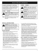
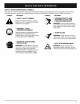
The purpose of safety symbols is to attract your attention to possible dangers. The safety symbols, and their explanations, deserve your careful attention and understanding. The safety warnings do not by themselves eliminate any danger. The instructions or warnings they give are not substitutes for proper accident prevention measures. I SYMBOL A Aiik MEANING ] SAFETY ALERT SYMBOL: Indicates danger, warning or caution. Attention is required in order to avoid serious personal injury.
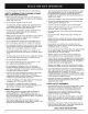
• Do not charge the unit in the rain or in wet locations SAFETY WARNINGS FOR CHARGING AND LEAD-ACID BATTERIES STANDS • Before using the charging stand, read all instructions and cautions in this manual, as well as on the charging stand, and on the unit. • Do not expose charger to rain or snow. • The cutting attachment shield must always be in place while operating the unit. Do not operate unit without the trimming lines extended, and the proper line installed.
SAFETY AND INTERNATIONAL SYMBOLS This operato['s manual describes safety and international symbols and pictographs that may appear on this product. Read the operator's manual for complete safety, assembly, operating and maintenance and repair information. SYMBOL MEANING Indicates danger, warning or caution. • SAFETY May be usedALERT in conjunction SYMBOL with other symbols or pictographs.
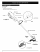
APPLICATIONS As a trimmer: • Cutting grass and light weeds • Decorative trimming around trees, fences, etc. Door \ Battery Housing Air Vents Hand Grip - Lock-Off Button Overload Protection Switch Trigger Motor Wire Housing Tube Motor Housing Cutting Attachment Shield \\\\\\\\\_1_ Bump Knob Line Cutting 6 Blade Bump Head Cutting Attachment
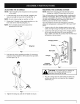
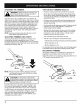
ADJUSTING THE D-HANDLE MOUNTING THE CHARGING STATION NOTE: The D-handle comes mounted on the backside of the shaft. NOTE: Mount the charging unit and allow the unit to charge for at least 36 hours prior to first use. 1. This unit may stay on the charging station continuously without overcharging. Place the charging station where the unit is intended to be stored. This should be a cool, dry and well ventilated place, where the unit can be locked-up and out of the reach of children.
CHARGING THE UNIT 3. Make sure the charging station is securely fastened to a wall and the charger is plugged into a working wall outlet. NOTE: The unit's operahng time and the life of the battery will be shorten if the untt is not fully charged between uses, NOTE: Allow the unit to charge for at least 36 hours prior to first use. 4. Slide the unit down into the charging station until it is firmly seated (Fig. 4). The barrel connector in the charging station will insert into the unit.
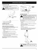
STARTINGTHE UNIT 1. Press and hold the lock-off button in (Fig. 6). This allows the trigger to operate. Overload Protection Switch WARNING: To prevent serious personal l injury, ensure th e lock-off button [esets each I time the trigger is released. I ] Fig. 7 HOLDING THE UNIT WARNING: Dress properly to reduce the risk of injury when operating this unit. Do not wear loose clothing or jewelry. Wear eye and ear/hearing protection. Wear heavy, long pants, boots and gloves.
OPERATINGTHETRIMMER TIPS FOR BEST TRIMMING RESULTS • Keep the cutting attachment parallel to the ground and body protection to reduce the risk of WARNING: Always wear injury when operating this eye, Unit hearing, foot I J Clear the area to be cut before each use Remove all objects such as rocks, broken glass, nails, wire, or string which can be thrown or become entangled in the cutting attachment Clear the area of children, bystanders, and pets At a minimum, keep all children, bystanders and pets outsi
Thewarrantyonthisunitdoesnotcoveritemsthathave beensubjectedto operatorabuseor negligence. To receivefullvaluefromthewarranty,the operatormust maintaintheunitas instructedinthisoperator'smanual. NOTE: Always clean the inner reel, outer spool and shaft before reassembling the bump head. WARNING: Battery tools do not have to be plugged into an electrical outlet; therefore, they are always in operating condition.
7. Insert the end of the line into one of the two holding slots (Fig. 14). 11. Install the bump head cover over the inner reel. Align the tabs on the cover with the slots in the outer spool and press the cover evenly down until it snaps into place. NOTE: Make sure the bump head cover tabs snap into place or the inner reel will come out during operation. INSTALLING A PREWOUND REEL Always use genuine replacement line. Using larger line then the specified may make the motor overheat or fail. 1. Slot Fig.
BATTERY .,,_ \_,_f Pb PACK REPLACEMENT To preserve natural resources, please recycle or dispose of properly. THIS PRODUCT I CONTAINS A SEALED LEAD-ACID BATTERY AND MUST BE DISPOSED OF PROPERLY. Local, State, Or federal laws may prohibit disposal of sealed lead-acid batteries in ordinary trash. Consult your local waste authority for information regarding available recycling and/or disposal options. Removing the Battery I.
REPLACING THE CHARGER CLEANING Replace the charger if it is damaged, if the barrel connector or cord become damaged, or if the barrel connector is not contacting the unit properly. WARNING: To avoid serious personal injury, always turn your trimmer off and remove the battery before you c ean or serv ce t. CAUTION: Only use the type of charger specified for this unit. Any other type may cause damage to the unit, damage to the batteries or possible injury.
CAUSE ACTION Battery is not charged Charge the battery Overload protection switch has popped Reset overload protection switch CAUSE ACTION No power to charger or battery Check charger and charging station Battery has failed Replace the battery CAUSE Cutting attachment bound with grass Cutting attachment out of line ACTION Stop the unit and clean cutting attachment Refill with new line Inner reel bound up Replace the inner reel Cutting attachment dirty Line welded Clean inner reel and outer
REPLACEMENT PARTS-MODEL TB55B 12 VOLT BATTERY TRIMMER (_ PPN 41AET55G063 ® Item Part NO.
MANUFACTURER'S LIMITED WARRANTY FOR: O TROII BIIT" The limited warranty set forth below is given by Troy-Bilt LLC with respect to new merchandise purchased and used in the United States, its possessions and territories. Troy-Bilt LLC warrants this product against defects in material and workmanship for a period of two (2) years commencing on the date of original purchase and will, at its option, repair or replace, free of charge, any part found to be defective in material or workmanship.