
User manual


This is a publication by Conrad Electronic SE, Klaus-Conrad-Str. 1, D-92240 Hirschau (www.conrad.com).
All rights including translation reserved. Reproduction by any method, e.g. photocopy, microlming, or the capture in
electronic data processing systems require the prior written approval by the editor. Reprinting, also in part, is prohibited.
This publication represent the technical status at the time of printing.
© Copyright 2017 by Conrad Electronic SE. 1571265_V1_1017_02_VTP_m_en
Installation and connection
In order to ensure correct commissioning, you should read these operating instruc-
tions including the safety instructions thoroughly and attentively before using the
device! If in doubt, leave the installation and connection to a specialist.
Only connect boards that are voltage free. Otherwise, there is a risk of a life-threat-
ening electric shock!
a) Installation
The relay board must be installed in a way that accidental contact is avoided (if voltages above
the low voltage range are switched via the relay contacts). Here also a sufcient distance to
low voltage or non-mains-carrying circuit parts must be observed. Secure the board so that it
does not come loose.
Warning! There is a risk of a life-threatening electric shock if the work is done incor-
rectly!
b) Connection
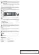
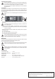
• Two-pole connection terminal “IN”: Control voltage (12 V/DC) connection for switching the
relay contacts
It is important to observe the correct polarity (plus/+ and minus/-); see label on the
board or the gure above.
When control voltage is applied, a control LED will go on next to the connection
terminals. You can route the LED light to the front of an enclosure using suitable light
conductors, for example.
• Two three-pole connection terminals “CO/NC/NO”: Relay switching contacts; two potential-
free switching contacts
CO = common switch contact
NC = Switch output “normally closed” (closed when idle)
NO = Switch output “normally open” (open when idle)
Secure all cables appropriately. Ensure appropriate strain relief of the mains cables
dependent on the place where the relay board is installed. This is especially true, if
voltages are switched that are above the low voltage range.
Maintenance
The relay circuit board is maintenance-free. However, check the connection leads for damage
from time to time and that the connections are mechanically secured.
Only an authorised expert may perform repairs.
Before you start working on the module, ensure it is fully disconnected from voltage/
current; the same also applies to all devices connected to the relay contacts.
Disposal
Electronic devices are recyclable material and do not belong in the household
waste. Please dispose of the unserviceable product in accordance with the relevant
statutory regulations.
Technical data
Control/operating voltage .......................12 V/DC
Switching capacity (resistive load) .......... max. 150 W, max. 1250 VA
Switching current ....................................max. 5 A
Switching voltage .................................... max. 125 V/DC, max. 250 V/AC
Switch contacts ...................................... relay, 2x changeover contacts, potential-free
Dimensions ............................................. 72 x 20 x 36.5 mm (L x W x H)