
Datasheet


Conrad Electronic SE, Klaus-Conrad-Str. 1, D-92240 Hirschau
Item no.: 2481782
Data Sheet
Page 2 of 3
Some typical stepper motor details:
•
Model: 28KYJ-48
•
Voltage: 5VDC
•
Phase: 4
•
Step Angle: 5.625°(1/64)
•
Reduction ratio: 1/64
It takes 4096 steps to rotate the spindle 360°. It is impossible to see a single step. When testing it pays to have
something distinct on the spindle to show it is turning.
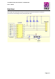
Physically connecting a microcontroller to the driver board is straight forward. Pick a free GPIO pin on an
expansion header and run a wire from it to one of the input pins on the driver board. The driver board requires
power. Make sure your power supply has sufficient power to drive the stepper motor. It is usually a good idea to
use a separate power source to the one that is driving the microcontroller. Having wired a GPIO pins to the driver
board you can test the interface. Set the GPIO pin high and the corresponding LED on the driver board will
illuminate. Set it low and the LED turns off.
Typical Connections
Signal Name
Microcontroller Pin
Driver Board Pin
VDD_5V
+
GND
GND
-
GPIO1
PORTA.0
IN1
GPIO2
PORTA.1
IN2
GPIO3
PORTA.2
IN3
GPIO4
PORTA.3
IN4
The motor steps when a specific combination of inputs are driven from the microcontroller. This is just a pulse
of power, just enough to get the motor to step. This driver uses a very simple protocol. Applying a signal to an
input pin causes power to be sent to the motor on a corresponding wire.
MCU IO Code Wire Color
The following codes define the step commands.
8 Step: A – AB – B – BC – C – CD- D – DA
4 Step: AB – BC – CD- DA (usual application)
Step Command IN4 IN3 IN2 IN1
A
01H
0
0
0
1
AB
03H
0
0
1
1
B
02H
0
0
1
0
BC
06H
0
1
1
0
C
04H
0
1
0
0
CD
0CH
1
1
0
0
D
08H
1
0
0
0
DA
09H
1
0
0
1
IN1
A
Blue
IN2
B
Pink
IN3
C
Yellow
IN4
D
Orange