
Manual
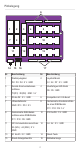
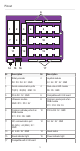
Table Of Contents

5
Pinout
1 2 3 4 5
7 8 9
12
6
17161514
10
11 13
Nr. Description Nr. Description
1 Rotary encoder
D2 : D3 : D4 : 5V : GND
2 Joystick module
A1 : A0 : D7 : 5V : GND
3 Serial communication ports
TX(D1) : RX(D0) : GND : 5V
4 Dual-colour LED module
D6 : D5 : GND
5 D5 to D2 : 5V : GND 6 Compatible with V4.0 board
7 Ultrasonic module
GND : D13 : D12 : 5V
8 Common anode ports of an
RGB module
D11 : D10 : D9 : 5V
9 Common cathode ports of an
RGB module
D11 : D10 : D9 : GND
10 D12 to D8 : 5V : GND
11 I2C communication port
A5 (SCL) : A4 (SDA) : 5V :
GND
12 A3 : A2 : 5V : GND
13 A1 to A5 : 5V : GND 14 Reset button
15 Reset indicator light 16 Power indicator light
17 Compatible with V4.0 board