TRUE RESIDENTIAL ® THE TRUE 42 / 4 8 I N S TA L L G U I D E A N D U S E R ’ S M A N U A L PRESERVE THE MOMENT®
THANK YOU FOR YOUR PURCHA SE
INDE X OWNERSHIP, S AFE T Y PRECAUTIONS, DISP O S AL OF OL D REFRIGER ATOR, CFC DISP O S AL 1-2 SITE PREPAR ATION, EL ECTRICAL REQUIREMENTS 3-8 PL AN V IE W S 9 -13 ANTI -TIP BR ACK E T INSTAL L ATION, L E V ELING THE UNIT 15 -18 BA SIC EL ECTRONIC C ONTROL OPER ATIONS 19 -2 5 SHELVING, REFRIGER ATOR STOR AGE, FREE ZER STOR AGE, REMOVING THE D O ORS, K ICK PL ATE INSTAL L ATION 2 7- 3 0 STAINL ES S STEEL EQUIPMENT CARE & CL E ANING, GENER AL MAINTENANCE, C ONDENS ATION, DATA TAG, WARR ANT Y STATEMENT, C ON
THE TRUE 42 / 48 TR-42SBS-SS-B TR-48SBS-SG-SS-B Commercial refrigeration refined for the home, envied in the industry, and crafted—gorgeously—in America.
1-2 Ownership Safety Precautions Disposal of the O ld Refrig er ator CFC D i s p o s a l PRESERVE THE MOMENT® THE TRUE 42 / 48 1
OWNERSHIP T O IN SUR E T H AT YOUR UNI T WO R K S P R OP ER LY F R OM T HE F IR S T D AY, I T MU S T BE IN S TA L L ED P R OP ER LY. NO T E: W E HIGHLY R EC OMMEND A T R A INED R EF R IG ER AT ION MECH A NIC A ND EL EC T R ICI A N IN S TA L L YOUR T RUE R E SID EN T I A L ® C A BINE T. T HE C O S T O F A P R O F E S SION A L IN S TA L L AT ION I S MONE Y W EL L SP EN T. Before you start to install your True Residential ® Cabinet, carefully inspect it for freight damage.
3-6 S ite Prepar ation Electrical Requirements PRESERVE THE MOMENT® THE TRUE 42 / 48 3
SITE PREPAR ATION • Rough Opening dimensions. (See figure 1 and 2) • For FLUSH installations the front face of the unit will be flush with the surrounding cabinets. (See figure 3) • For PROUD (Standard) installations, the front face of the unit will extend beyond cabinets. (See figure 4) NOTE: IT IS NOT RECOMMENDED TO INSTALL UNITS SIDE BY SIDE WITH HINGES TOUCHING EACH OTHER. IF YOU PLAN TO INSTALL UNITS HINGE TO HINGE, CALL TECH SUPPORT AT 844-746-9423 FOR INSTALLATION INSTRUCTIONS.
TR-42 TOP VIEW FIGURE 3 - FLUSH INSTALLATION 23/16" TOP VIEW FIGURE 4 - PROUD INSTALLATION 43/16" NO T E: DIMEN SION S M AY VA RY BY ± 1 / 8 ” THE TRUE 42 / 48 5
TR-48 TOP VIEW FIGURE 1 - ROUGH OPENING FRONT VIEW FIGURE 2 - ROUGH OPENING Electrical located in this area 8" 26" MINIMUM FLUSH INSTALL 2" FLUSH INSTALL 841/4" FLUSH INSTALL 84" PROUD INSTALL 77" 24" MINIMUM PROUD INSTALL PROUD INSTALL 473/4" PROUD INSTALL 481/4" FLUSH INSTALL NO T E: DIMEN SION S M AY VA RY BY ± 1 / 8 ” 6 TRUE RESIDENTIAL®
TR-48 TOP VIEW FIGURE 3 - FLUSH INSTALLATION 23/16" TOP VIEW FIGURE 4 - PROUD INSTALLATION 43/16" NO T E: DIMEN SION S M AY VA RY BY ± 1 / 8 ” THE TRUE 42 / 48 7
ELEC TRIC AL REQUIREMENT S For all built-in models, the electrical supply should be located within the shaded area shown in the illustration (See Figure 5). Follow the National Electrical Code and local codes and ordinances when installing the receptacle. A dedicated circuit, supplying only this appliance is required. A ground fault circuit interrupter (GFCI) is not recommended and may cause interruption of operation.
7 - 11 PLAN VIEWS TR - 4 2 S B S - SS - B TR - 4 8 S B S - SS - B PRESERVE THE MOMENT® THE TRUE 42 / 48 9
OVER ALL DIMENSIONS - TR-42 TOP VIEW 419/16" CABINET WIDTH 2325/32" 21/2" DOORS OPEN 90º 2013/16" 265/8" DOORS OPEN 135º 131/32" 10 TRUE RESIDENTIAL® 175/32" NO T E: DIMEN SION S M AY VA RY BY ± 1 / 8 ”
FRONT VIEW 8331/32" 6729/32" DOOR HEIGHT 7221/32" 3015/32" 2729/32" 2525/32" 833/4" CABINET HEIGHT 315/16" SIDE VIEW NO T E: DIMEN SION S M AY VA RY BY ± 1 / 8 ” THE TRUE 42 / 48 11
OVER ALL DIMENSIONS - TR-48 TOP VIEW 47 9/16" CABINET WIDTH 2325/32" 21/2" DOORS OPEN 90º 2013/16" 325/8" DOORS OPEN 135º 13 1/16" 12 TRUE RESIDENTIAL® NO T E: DIMEN SION S M AY VA RY BY ± 1 / 8 ” 21 7/16"
FRONT VIEW 20" 6729/32" DOOR HEIGHT 573/4" GLASS OPENING 8331/32" 7221/32" 3015/32" 2729/32" 2525/32" 833/4" CABINET HEIGHT 315/16" SIDE VIEW NO T E: DIMEN SION S M AY VA RY BY ± 1 / 8 ” THE TRUE 42 / 48 13
NOTE S
11 - 14 A n t i -t i p B r a c k e t I n s ta l l at i o n Leveling the Unit PRESERVE THE MOMENT® THE TRUE 42 / 48 15
987036 TRUE RESIDENTIAL REFRIGERATION 5.19.17 AL UPRIG HT ANTI-TIP BR ACKE T INS TALL ATION 2. Using the bracket as a guide, drill pilot holes into the wall/floor. It is recommended to secure the bracket to as many floor joists and wall studs as possible. ANTI-TIP BR ACKE T KIT: • One (1) anti-tip bracket (Figure 1.
Anti-Tip Kit Install TR-42SBS-SS-B R N O T E : D I M E N S I O N S M AY VA R Y B Y ± 1 / 8 ” 42 INCH UNIT 20 25/32" 528mm 9 9/32" 236mm CL CL 9 9/32" 236mm CL 22 31/32" 583mm PROUD INSTALL 24 31/32" 634mm FLUSH INSTALL Anti-Tip Kit Install TR-48SBS-SS-B R N O T E : D I M E N S I O N S M AY VA R Y B Y ± 1 / 8 ” 48 INCH UNIT 23 25/32" 604mm 9 9/32" 236mm 9 9/32" 236mm CL 24 31/32" 634mm FLUSH INSTALL CL CL 22 31/32" 583mm PROUD INSTALL NO T E S : • DUE T O T HE W EIGH T O F UNI T S, I T I
LE VELING THE UNIT It is very important that the refrigerator sits level. This will insure that the doors will align and seal properly and that the drain pans will not spill over. T O L E V EL T HE UNI T: 1. P L A CE A L E V EL ON T HE IN T ER IO R F L O O R . CHECK A ND A D JU S T F O R L E V EL F R OM F R ON T T O B A CK , A L SO CHECK A ND A D JU S T F O R L E V EL F R OM R IGH T T O L EF T. 2. A D JU S T T HE F R ON T S U SING A SE T O F P L IER S O R A W R ENCH. (SEE F IGUR E 6) 3.
15 - 22 Elec tronic Control O per ations PRESERVE THE MOMENT® THE TRUE 42 / 48 19
ELEC TRONIC CONTROL OPER ATIONS P L E A SE NO T E T H AT T HOUGH P O S SIBL E T O DI SP L AY T EMP ER AT UR E S IN FA HR ENHEI T O R CELSIU S, IN MO S T C A SE S FA HR ENHEI T R E A DING S A R E SHO W N IN T HI S M A NUA L . UNIT ON/OFF All units are shipped in ON Mode. When electricity is supplied to the appliance, a short power up diagnostics test is initiated followed by one audible beep, the lights energizing and temperature readings appearing in the LCD.
TEMPER ATURE ADJUS TMENT (ZONE NAVIG ATION) To adjust set-points, press ZONE for the appropriate compartment, then DOWN or UP key on control panel in multiple key strokes until the desired set-point is achieved (See Figure 9). Each key stroke equals a one degree change and is accompanied by an audible beep. When the desired set-point is reached press the ZONE key until you reach the “HOME” screen, where the current zone temperatures will be displayed.
MODE NAVIG ATION The following pages illustrate unique customer input operations performed at the control panel. The input operations described are: HOLIDAY MODE, TEMPERATURE UNIT SELECTION MODE AND VACATION MODE. NO T E S: ( HO L IDAY MO D E ) • SE T- P OIN T S C A NNO T BE CH A NG ED A ND M A NUA L D EF R O S T C A NNO T BE INI T I AT ED. • T HE F O L L OW ING HO L D S T RUE IN A C C O R D A NCE W I T H S TA R- K R EQUIR EMEN T S: - Freezer defrosting functions will convert to a fixed time base sequence.
ACCENT LIG HTING SYS TEM All models are equipped with an accent lighting system in the refrigerator and or freezer compartment(s). To energize the accent lighting system, press the LIGHT key, and navigate to the corresponding compartment, DOOR or ON will appear in the LCD indicating the accent lights are enabled. With the accent lighting system ON, the LED’s will be energized and stay illuminated when the door is closed, in the DOOR position the lighting system will only be energized with the door opening.
AL ARM NAVIG ATION (DOOR A JAR AL ARM FE ATURE ON/OFF) All Residential Series units are equipped with a door ajar alarm feature. To enable the door ajar alarm, press the ALARM key on the control panel and “DOOR AJAR ALARM ON” will appear in the LCD indicating the alarm is enabled (See Figure 12). With the alarm enabled, the notification icons will appear and an audible alarm will beep continuously whenever a door is left open for more than 5 minutes.
NOTIFIC ATION ALERT S The diagrams on these pages illustrate what a customer may see in the LCD if the appliance needs attention (See Figure 13).
NOTE S
23 - 26 S h elv i n g Refrig er ator Stor ag e Free zer Stor ag e Removing the D oo r s Kick Pl ate Ins tall ation PRESERVE THE MOMENT® THE TRUE 42 / 48 27
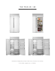
SHELVING All shelving and door bins come packaged inside the unit. (See Figure 14) FIGURE 14 REFRIG ER ATOR S TOR AG E G L A S S SHELV E S Remove the top foam piece holding the glass shelves. Carefully remove shelves and set aside. (See Figure 15). Remove all other packing material. To install, insert glass shelf into the shelf standards on the back wall, with the front tilted upward, and then lower the front until it stops. (See Figure 16).
D R AW ER S To remove a drawer, pull drawer forward until it stops. Use a Phillips screw driver to remove the two (2) screws securing the drawer to the slides, then lift the drawer up and out of unit. (See Figure 19). To reinstall, pull drawer slides all the way forward on unit, and then slide the drawer onto the slides until the hook on the back of the slide is over top of the drawer, reinstall the screws using the Phillips screw driver.
REMOVING THE DOORS R EMO V ING T HE D O O R S Open the door to 90 degrees. (See Image 23). Lift the door straight up and out of the hinges. (See Image 24). To re-install, hold the door 90 degrees to the opening and align hinge posts to the hinges. Lower the door into place. FIGURE 23 FIGURE 24 KICK PL ATE INS TALL ATION K ICK P L AT E The kick plate is shipped with the unit but not attached to allow access to level the unit (See Image 25).
27-28 Stainle ss Steel Equipment C are and Cleaning General Maintenance Condensation D a t a Ta g Warr ant y Statement Contac t Inform ation PRESERVE THE MOMENT® THE TRUE 42 / 48 31
S TAINLE SS S TEEL EQUIPMENT C ARE AND CLE ANING C AU T ION: D O NO T U SE A N Y S T EEL WO O L , A BR A SI V E O R CHL O R INE B A SED P R O DUC T S T O CL E A N S TA INL E S S S T EEL SUR FA CE S. STAINLESS STEEL OPPONENTS There are three basic things which can break down your stainless steel’s passivity layer and allow corrosion to rear its ugly head. 1. Scratches from wire brushes, scrapers, and steel pads are just a few examples of items that can be abrasive to stainless steel’s surface. 2.
G ENER AL M AINTENANCE Keeping the condenser coil clean will minimize required service and lower electrical cost. The condenser coil is accessible from the front. (See Figure 27). The condenser coil should be cleaned by removing dust and other build-up from the tube assembly with vacuum or a cleaning rag. When properly cleaned you should be able to see through the tube assembly. Warranty does not cover cleaning the condenser coil.
TRUE RESIDENTIAL® SERIES LIMITED WARRANTY STATEMENT LIMITED 30 DAY COSMETIC WARRANTY Stainless steel doors, handles, and shelves are warranted to be free from defective materials or workmanship for a period of thirty (30) days from the date of original retail purchase. Any defects must be reported to the selling dealer within thirty (30) days from the date of original retail purchase. This limited warranty excludes any type of freight / concealed damage.
CONTAC T INFORM ATION Please have your serial # on hand so we can better assist you. The serial # is a 7-digit number located on the left hand side wall by the pull out wire basket located in the freezer section of your unit. Customer Service Phone 888-616-8783 Website – www.true-residential.com Warranty Department Phone 844-849-6179 Website – trueresidentialwarranty@truemfg.com Service Department Phone 844-746-9423 Website - service@truemfg.
NOTE S
NOTE S
NOTE S
CONTACT US w w w.t r ue -r e siden tial.com ( 6 36) 24 0 -24 0 0 • toll free ( 8 8 8 ) 616 - 878 3 987023 SD · 12.