TRUE RESIDENTIAL ® TR-30 I N S TA L L AT I O N / U S E R G U I D E PRESERVE THE MOMENT®
INDE X OWNERSHIP, S AFE T Y PRECAUTIONS, DISP O S AL OF OL D REFRIGER ATOR, CFC DISP O S AL 1-2 SITE PREPAR ATION, EL ECTRICAL REQUIREMENTS 3-6 PL AN V IE W S 7-11 ANTI -TIP BR ACK E T INSTAL L ATION, L E V ELING THE UNIT 12-15 BA SIC EL ECTRONIC C ONTROL OPER ATIONS REFRIGER ATOR AND FREE ZER 16 -2 2 BA SIC EL ECTRONIC C ONTROL OPER ATIONS DUAL ZONE 2 3 -2 9 SHELVING, REFRIGER ATOR STOR AGE, FREE ZER STOR AGE, REMOVING THE D O ORS, K ICK PL ATE INSTAL L ATION 30-32 STAINL ES S STEEL EQUIPMENT CARE & CL E
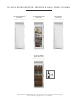
0 INCH REFRIG ER ATOR , FREEZER & DUAL ZONE COLUMN 30” REFRIGERATOR COLUMN 30” REFRIGERATOR COLUMN 30” FREEZER COLUMN STAINLESS SOLID DOOR STAINLESS GLASS DOOR STAINLESS SOLID DOOR 30” DUAL ZONE WINE COLUMN STAINLESS GLASS DOOR Commercial refrigeration refined for the home, envied in the industry, and crafted—gorgeously—in America.
1-2 Ownership Safety Precautions Disposal of the O ld Refrig er ator CFC D i s p o s a l PRESERVE THE MOMENT® 30 INCH COLUMNS 1
OWNERSHIP T O IN SUR E T H AT YOUR UNI T WO R K S P R OP ER LY F R OM T HE F IR S T D AY, I T MU S T BE IN S TA L L ED P R OP ER LY. NO T E: W E HIGHLY R EC OMMEND A T R A INED R EF R IG ER AT ION MECH A NIC A ND EL EC T R ICI A N IN S TA L L YOUR T RUE R E SID EN T I A L ® C A BINE T. T HE C O S T O F A P R O F E S SION A L IN S TA L L AT ION I S MONE Y W EL L SP EN T. Before you start to install your True Residential ® Cabinet, carefully inspect it for freight damage.
3-5 S ite Prepar ation Electrical Requirements PRESERVE THE MOMENT® 30 INCH COLUMNS 3
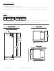
SITE PREPAR ATION • Rough Opening dimensions. (See figure 1) • For FLUSH installations the front face of the unit will be flush with the surrounding cabinets. (See figure 2) • For PROUD (Standard) installations, the front face of the unit will extend beyond cabinets.
135° TOP VIEW 29 9/16" 751mm 83 15/16" 2132mm 23 25/32" 604mm 20 11/16" 525mm 8" mm 3 15/16" 100mm 23 25/32" 604mm 55 1/4" 1403mm 90° 135° R FRONT VIEW 30" 762mm 90° 55 1/4" 1403mm 2 9/16" 65mm 30" 762mm 31 15/32" 799mm 2 9/16" 65mm 29 15/32" 748mm 67 29/32" 1725mm DOOR67 29/32" HEIGHT1725mm DOOR HEIGHT TR 29 15/32" 748mm R 29 9/16" 751mm 31 15/32" 799mm SIDE VIEW 30 15/32" 774mm 30 15/32" 27 29/32" 774mm 709mm 27 29/32" 25 25/32" 709mm 655mm 25 25/32" 655mm 83 15/16" 2132mm 83 15/
ELEC TRIC AL REQUIREMENT S For all built-in models, the electrical supply should be located within the shaded area shown in the illustration. Follow the National Electrical Code and local codes and ordinances when installing the receptacle. A separate circuit, servicing only this appliance is required. A ground fault circuit interrupter (GFCI) is not recommended and may cause interruption of operation.
7 - 11 Pl an Views TR - 3 0 / TR - 4 2 TR - 3 0 / TR - 4 8 TR - 3 0 / TR - 3 0 TR - 3 0 / TR - 3 0 / TR - 3 0 PRESERVE THE MOMENT® 30 INCH COLUMNS 7
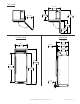
TR-30 / TR-42 23 25/32" 604mm PROUD INSTALL FLUSH OPENING DIMENSIONS Width Depth 72¼" 25 25/32" Height 84 1/4" PROUD OPENING DIMENSIONS Width Depth 71¾" FLUSH VS .
TR-30 / TR-48 23 25/32" 604mm PROUD INSTALL FLUSH OPENING DIMENSIONS Width Depth 78¼" 25 25/32" Height 84 1/4" PROUD OPENING DIMENSIONS Width Depth 77¾" FLUSH VS .
TR-30 / TR-30 23 25/32" 604mm PROUD INSTALL FLUSH OPENING DIMENSIONS Width Depth 60¼" Height 25 25/32" 84 1/4" PROUD OPENING DIMENSIONS Width Depth 59¾" FLUSH VS .
TR-30REF,30FRZ,30DZW R TR-30 / TR-30 / TR-30 FLUSH OPENING DIMENSIONS Width Depth 23 25/32" 604mm PROUD INSTALL 90¼" 25 25/32" Height 84 1/4" PROUD OPENING DIMENSIONS Width Depth 89 3/4" 23 25/32" FLUSH VS .
12 - 15 A n t i -t i p B r a c k e t I n s ta l l at i o n Leveling the Unit PRESERVE THE MOMENT® 12 TRUE RESIDENTIAL®
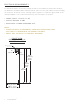
987036 TRUE RESIDENTIAL REFRIGERATION 5.19.17 AL UPRIG HT ANTI-TIP BR ACKE T INS TALL ATION 2. Using the bracket as a guide, drill pilot holes into the wall/floor. It is recommended to secure the bracket ANTI-TIP BR ACKE T KIT: • One (1) anti-tip bracket (Figure 1.1) • Four (4) masonry 3/16” screws • Eight (8) wood #12 – 2” screws to as many floor joists and wall studs as possible.
Anti-Tip Kit Install TR-42SBS-SS-B R N O T E : D I M E N S I O N S M AY VA R Y B Y ± 1 / 8 ” 42 INCH UNIT 20 25/32" 528mm 9 9/32" 236mm CL CL 9 9/32" 236mm CL 22 31/32" 583mm PROUD INSTALL 24 31/32" 634mm FLUSH INSTALL Anti-Tip Kit Install TR-48SBS-SS-B R N O T E : D I M E N S I O N S M AY VA R Y B Y ± 1 / 8 ” 48 INCH UNIT 23 25/32" 604mm 9 9/32" 236mm 9 9/32" 236mm CL 24 31/32" 634mm FLUSH INSTALL CL CL 22 31/32" 583mm PROUD INSTALL NO T E S : • DUE T O T HE W EIGH T O F UNI T S, I T I
LE VELING THE UNIT It is very important that the refrigerator sits level. This will insure that the doors will align and seal properly and that the drain pans will not spill over. TO LE VEL THE UNIT: STEP 1. Place a level on the interior floor. Check and adjust so the unit is level from front to back, and left to right. STEP 2. Adjust the front legs using a set of pliers or a wrench. STEP 3. Adjust the rear using a 7/16" socket and ratchet. Turn clockwise to raise the rear of the unit.
16 - 22 Ba sic Elec tronic Control O per ations Refrig er ator and Freezer PRESERVE THE MOMENT® 16 TRUE RESIDENTIAL®
BA SIC ELEC TRONIC CONTROL OPER ATIONS UNIT ON/OFF All units are shipped in ON Mode. When electricity is supplied to the appliance, a short power up diagnostics test is initiated followed by one audible beep, the lights energizing and temperature readings appearing in the LCD.
TEMPER ATURE ADJUS TMENT To adjust set-point, press DOWN or UP key on control panel in multiple key strokes until the desired set-point is achieved. Each key stroke equals a one degree change and is accompanied by an audible beep. When the desired set-point is reached wait 5 seconds until display resumes “HOME” screen. NO T E S: • T HE T EMP ER AT UR E R A NG E IN A F R EE Z ER Z ONE I S - 4°F (-2 0 °C) T O + 4°F (-16°C).
MODE NAVIG ATION The following pages illustrate unique customer input operations performed at the control panel. The input operations described are: HOLIDAY MODE, TEMPERATURE UNIT SELECTION MODE AND VACATION MODE. NO T E S: ( HO L IDAY MO D E ) • SE T- P OIN T S C A NNO T BE CH A NG ED A ND M A NUA L D EF R O S T C A NNO T BE INI T I AT ED. • T HE F O L L OW ING HO L D S T RUE IN A C C O R D A NCE W I T H S TA R- K R EQUIR EMEN T S: - Freezer defrosting functions will convert to a fixed time base sequence.
ACCENT LIG HTING SYS TEM All models are equipped with an accent lighting system in the refrigerator and or freezer compartment(s). To energize the accent lighting system, press the LIGHT key, and navigate to the corresponding compartment, DOOR or ON will appear in the LCD indicating the accent lights are enabled. With the accent lighting system ON, the LED’s will be energized and stay illuminated when the door is closed, in the DOOR position the lighting system will only be energized with the door opening.
AL ARM NAVIG ATION (DOOR A JAR AL ARM FE ATURE ON/OFF) All Residential Series units are equipped with a door ajar alarm feature. To enable the door ajar alarm, press the ALARM key on the control panel and “DOOR ALARM IS ON” will appear in the LCD indicating the alarm is enabled. With the alarm enabled, the notification icons will appear and an audible alarm will beep continuously whenever a door is left open for more than 5 minutes.
NOTIFIC ATION ALERT S The diagrams on these pages illustrate what a customer may see in the LCD if the appliance needs attention.
23 - 29 Ba sic Elec tronic Control O per ations Dual Zone PRESERVE THE MOMENT® 30 INCH COLUMNS 2 3
BA SIC ELEC TRONIC CONTROL OPER ATIONS UNIT ON/OFF All units are shipped in ON Mode. When electricity is supplied to the appliance, a short power up diagnostics test is initiated followed by one audible beep, the lights energizing and temperature readings appearing in the LCD.
TEMPER ATURE ADJUS TMENT To adjust set-point, press the ZONE button to highlight the zone for adjustment. Once the zone is highlighted, press DOWN or UP key on the control panel in multiple key strokes until the desired set-point is achieved. Each key stroke equals a one degree change and is accompanied by an audible beep. When the desired set-point is reached, press the ZONE button to return to “HOME” screen. NO T E S: • T HE T EMP ER AT UR E R A NG E S F R OM 4 0 °F (4 . 4°C) T O 6 5°F (18 .
MODE NAVIG ATION The following pages illustrate unique customer input operations performed at the control panel. The input operations described are: HOLIDAY MODE, TEMPERATURE UNIT SELECTION MODE AND VACATION MODE. NO T E S: ( HO L IDAY MO D E ) • SE T- P OIN T S C A NNO T BE CH A NG ED A ND M A NUA L D EF R O S T C A NNO T BE INI T I AT ED. • T HE F O L L OW ING HO L D S T RUE IN A C C O R D A NCE W I T H S TA R- K R EQUIR EMEN T S: - Freezer defrosting functions will convert to a fixed time base sequence.
ACCENT LIG HTING SYS TEM All models are equipped with an accent lighting system in the refrigerator and or freezer compartment(s). To change the accent lighting color, press the LIGHT key once until you see “CHANGE COLOR” press the LIGHT button once again to start . Press the “LIGHT” button once again to lock in your desired color. DOOR or ON will appear in the LCD indicating the accent lights are enabled.
AL ARM NAVIG ATION (DOOR A JAR AL ARM FE ATURE ON/OFF) All Residential Series units are equipped with a door ajar alarm feature. To enable the door ajar alarm, press the ALARM key on the control panel and “DOOR ALARM IS ON” will appear in the LCD indicating the alarm is enabled. With the alarm enabled, the notification icons will appear and an audible alarm will beep continuously whenever a door is left open for more than 5 minutes.
NOTIFIC ATION ALERT S The diagrams on these pages illustrate what a customer may see in the LCD if the appliance needs attention.
30 - 32 S h elv i n g Refrig er ator Stor ag e Free zer Stor ag e R e m ov i n g the D oo r s Kick Pl ate Ins tall ation PRESERVE THE MOMENT® 30 TRUE RESIDENTIAL®
SHELVING All shelving and door bins come packaged inside the unit. REFRIG ER ATOR S TOR AG E G L A S S SHELV E S Remove the top foam piece holding the glass shelves. Carefully remove shelves and set aside. Remove all other packing material. To install, insert glass shelf into the shelf standards on the back wall, with the front tilted upward, and then lower the front until it stops. To remove or adjust a glass shelf, tilt up, and then lift up and out.
FREEZER S TOR AG E W IR E SHELV E S Remove the top foam piece holding the wire shelves. Carefully remove shelves and set aside. Remove all other packing material. To install, insert wire shelf into the shelf standards on the back wall, with the front tilted upward, and then lower the front until it stops. To remove or adjust a wire shelf, tilt up, and then lift up and out. FINAL WIRE SHELF INSTALLATION W IR E B A SK E T S To remove a basket, pull drawer forward until it stops.
33 - 36 Stainle ss Steel Equipment C are and Cleaning General Maintenance Condensation D a t a Ta g Contac t Us Warr ant y Statement PRESERVE THE MOMENT® 30 INCH COLUMNS 3 3
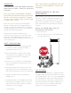
S TAINLE SS S TEEL EQUIPMENT C ARE AND CLE ANING C AU T ION: D O NO T U SE A N Y S T EEL WO O L , A BR A SI V E O R CHL O R INE B A SED P R O DUC T S T O CL E A N S TA INL E S S S T EEL SUR FA CE S. STAINLESS STEEL OPPONENTS There are three basic things which can break down your stainless steel’s passivity layer and allow corrosion to rear its ugly head. 1. Scratches from wire brushes, scrapers, and steel pads are just a few examples of items that can be abrasive to stainless steel’s surface. 2.
G ENER AL M AINTENANCE Keeping the condenser coil clean will minimize required service and lower electrical cost. The condenser coil is accessible from the front. The condenser coil should be cleaned by removing dust and other build-up from the tube assembly with vacuum or a cleaning rag. When properly cleaned you should be able to see through the tube assembly. Warranty does not cover cleaning the condenser coil.
TRUE RESIDENTIAL® SERIES LIMITED WARRANTY STATEMENT LIMITED 30 DAY COSMETIC WARRANTY Stainless steel doors, handles, and shelves are warranted to be free from defective materials or workmanship for a period of thirty (30) days from the date of original retail purchase. Any defects must be reported to the selling dealer within thirty (30) days from the date of original retail purchase. This limited warranty excludes any type of freight / concealed damage.
NOTES
NOTES