TRUE systems P2analog 2-CHANNEL PRECISION MICROPHONE PREAMPLIFIER with M/S decoding, Direct Inputs and Stereo Phase Correlation Display OPERATION MANUAL Version 1.
SAFETY and OPERATING PRECAUTIONS Important Information: This symbol indicates the presence of dangerous voltage within the product enclosure that presents the risk of electric shock injury. When this symbol appears next to an operation discussed in this manual, only qualified technical personnel should perform that operation. This symbol indicates important operating or maintenance instructions that should be read carefully.
CERTIFICATIONS FCC Notice This product complies with the limits for a Class A digital device, pursuant to Part 15 of the FCC rules. These limits are designed to provide reasonable protection against harmful interference when operated in a commercial environment. This equipment generates, uses, and can radiate radio frequency energy and, if not installed and used in accordance with instructions in this manual, may cause harmful interference to radio communications.
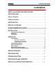
P2analog OPERATION MANUAL CONTENTS SAFETY and OPERATING PRECAUTIONS..............… … … … ....… ....2 CERTIFICATIONS… ..… … … … … … … … … … … … … … … … … … … … … … ...3 Owner’s Record… … … … … … … … … … … … … … … … … … … … … … … … … .3 Table of Contents… … … … … … … … … … … … … … … … … … … … … … … … .4 INTRODUCTION… .......................................................................… … … … ..5 PRODUCT OVERVIEW… ..................................................................… … ..
P2analog OPERATION MANUAL INTRODUCTION The P2analog is designed to provide the detailed, transparent sonic performance necessary for the most critical direct tracking and live sound applications. It includes a unique combination of functions that make it useful as a complete input system for standalone or PC-based recording systems. And, the P2analog has special features that provide the serious musician or recordist with useful tools to get the best sound more quickly and easily.
P2analog OPERATION MANUAL UP-AND-RUNNING IN A HURRY 1. Read the “SAFETY and OPERATING PRECAUTIONS”on page 2 of this manual. 2. Check the voltage selector on the rear panel to make sure it is set for the appropriate AC mains voltage in your area. 3. After making sure the main power switch is off, connect the AC power cord. 4. Connect output signal cables between P2analog and the analog line level inputs of your recorder, mixer, signal processor, etc.
P2analog OPERATION MANUAL Using the Stereo Phase Correlation Display If you wish to use the Stereo Phase Correlation Display to assist with stereo mic positioning: 1. Press the ON/OFF button to activate the display. 2. Adjust microphone positions so that most display activity occurs in the yellow and green LED’ s, with minimal activity in the red LED’ s. See the section “Stereo Phase Correlation Display”for more information. 3.
P2analog OPERATION MANUAL Ventilation We recommend that you provide adequate ventilation so that the air temperature surrounding the unit does not exceed 55C (122F). If multiple units are to be mounted in a poorly ventilated rack or travel case, a 1 3/4”blank space should be located after every three units (three units mounted together, blank space, three more units, etc.).
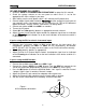
P2analog OPERATION MANUAL Do not attempt to connect unbalanced microphones (with single-pin connectors) to the P2analog. It is not intended to operate with this type of microphone. You may note the M-S (mid-side) connection symbol 5 below the MIC 1 and MIC 2 connectors. This is simply a visual reminder, when using an M-S mic setup, to connect the MID mic to channel 1 and the SIDE mic to channel 2. See the section “More About M-S Decoding”for more information.
P2analog OPERATION MANUAL Our studio testing has shown that some of the more esoteric guitar/instrument “super-cables”do, indeed, sound better. Noticeable improvement, but at a stiff price. Try before you buy! Avoid excessive cable length. Replace damaged connectors.
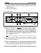
P2analog OPERATION MANUAL can happen with a conventional pad circuit. Normal microphone gain range (15.5dB to 64dB) is selected when the indicator is ON. Low gain range (3.5dB to 52dB) is selected when the indicator is OFF. 5 Phantom power selector (48V). Phantom power (+48VDC) is activated when the 48V indicator is illuminated. Avoid selecting phantom power if you are using a ribbon microphone. While not required, it is advisable to de-select 48V when using a dynamic microphone or a DI input.
P2analog OPERATION MANUAL NOTE: When M-S is selected, GAIN and polarity (180) are set to normal on both Channel 1 and Channel 2. The GAIN selectors for both channels are “locked” together so that pressing either one causes a similar gain range setting in both channels. 8 The Stereo Phase Correlation display selector (ON/OFF) determines whether the LED display is illuminated or not. In some circumstances the display can be very active or distracting.
P2analog OPERATION MANUAL What good is M-S versus the typical XY microphone placement? Originally, M-S was used because it provided a stereo signal with good mono compatibility. While this is not very interesting for contemporary stereo CD’ s, it is still valuable for broadcast and film sound production. But there is another significant benefit: varying the gain of the Side mic in relation to the Mid mic causes a variation in the stereo image - from none, to extreme separation.
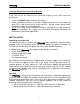
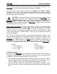
P2analog OPERATION MANUAL STEREO PHASE CORRELATION Output signals are essentially MONO 0 90 180 STEREO PHASE CORRELATION Typical STEREO display 0 90 180 STEREO PHASE CORRELATION 0 90 Excessive PHASE ERRORS (Adjust microphone) 180 STEREO PHASE CORRELATION 0 90 POLARITY REVERSAL (Reverse polarity on one microphone) 180 Here are some tips for using the Stereo Phase Correlation Display: When attempting to get a good stereo image, position the mics so that most of the Phase Display intensity
P2analog OPERATION MANUAL As always, your ears are the final reference! The Stereo Phase Correlation Display is provided as an accessory to help you with a potentially difficult and subjective part of the recording/sound reinforcement process. But when all is said and done, what you hear is more important than what you see on this Display. The Phase Display can become quite “busy”with complex sound sources. After mic positioning has been determined, you may wish to turn off the flickering Display.
P2analog OPERATION MANUAL TROUBLESHOOTING T Symptom Solution No signal output. Main power switch Check AC power source and cord. is on, but no LED’ s are illuminated. Check fuses (pull fuse drawer under power cord inlet) No signal output. Main power switch Check status of phantom power. is on and some LED’ s are Check continuity of mic and illuminated. instrument cables. Check continuity of output cables. electric Output signal is distorted.
P2analog when used with Channel 1 as a stereo pair OPERATION MANUAL OFF for individual channel mode and ON for Mid-Side mode. Make sure the 180selectors for both Channels 1 and 2 are OFF. In M-S mode the stereo channels Make sure the front of the bi-directional “Side” are reversed (Channel 1 is Right mic is aimed 90 degrees to the left of the axis and Channel 2 is Left) of the “Mid”mic. Alternatively, select 180 on Channel 2 to reverse channel positions.
P2analog OPERATION MANUAL Authorization (RMA) number from SUNRISE prior to returning a product. SUNRISE may require proof of the purchase date in the form of a copy of a dated original retail invoice. This warranty is void if, in the sole judgment of SUNRISE, the product has been abused, neglected, misapplied, or has been damaged by an accident, modification, or attempted repair by unauthorized personnel. This warranty will not apply to cosmetic damage incurred due to normal handling and use.