
Instruction Manual


P2
analog
OPERATION MANUAL
11
can happen with a conventional pad circuit. Normal microphone gain range (15.5dB
to 64dB) is selected when the indicator is ON. Low gain range (3.5dB to 52dB) is
selected when the indicator is OFF.
5 Phantom power selector (48V). Phantom power (+48VDC) is activated when the 48V
indicator is illuminated. Avoid selecting phantom power if you are using a ribbon
microphone. While not required, it is advisable to de-select 48V when using a
dynamic microphone or a DI input.
6 Level indicators. Use these to match signal level between the P2
analog
and
devices to which it is connected - and to avoid overloading the preamp.
SIG indicates that a signal is present on the channel. It illuminates when the signal
level exceeds -24dBu.
+4 illuminates when the signal reaches normal operating level of +4 dBu.
OL illuminates when the signal level exceeds +26 dBu, which is 5 dB below the
overload point for the P2
analog
*.
.Note that the overload level of the P2
analog
is +31dBu at the output*. This level
exceeds the input capability of some devices (check manufacturer’s specifications).
In such cases it is appropriate to use the intermediate level indicators (+15, +18,
+21, +24) to set the maximum output level of the P2
analog
to match the maximum
input capability of the connected device. In other words, it is possible to cause
overload distortion in the connected device even though the P2
analog
level
indicator does not show a red light. * Maximum output level in the low gain range is
+27dBu.
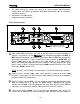
7 Mid-Side mode selector (M-S). When the M-S indicator is ON, Channel 1 output
becomes “Left” and Channel 2 output becomes “Right”. The Channel 1 gain control
adjusts the mono signal level applied to both the Left and Right outputs. The
Channel 2 gain control adjusts the stereo image width.
STEREO PHASE CORRELATION
0
90
180
M-S
ON/OFF
P2
analog
2-channel microphone preamplifier
I
0
7
8